• Please review our updated Terms and Rules here

A pair of Pets - Preparing to test after perhaps 40 years unused

First of all, check the HDRIVE and VDRIVE signals.

VDRIVE should be either 50 Hz or 60 Hz (depending upon the configuration of the EDIT ROM programming). The EDIT ROM part number will tell us...

HDRIVE should be something between 15 kHz and 20 kHz. I can't remember exactly what at the moment without looking it up.

Then check the VIDEO signal to see what you have - either stuck HI or LO, or activity.

Dave
I’m replying away from the machine but I know what these are:

Vdrive is very close to 50Hz
H drive is very close to 20Khz
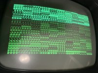
Video looks like activity - that is what I was measuring when C57 burned out on me yesterday 😀

I’ll post photos of the video tomorrow.
 
Last edited:
OK,

So you 'probably' have a working PET logic board. Certainly enough to get 'something' on the screen...

In terms of the monitor, check for all of the fusible resistors being intact (switched off).

Then check the DC output from the onboard voltage regulator (switched on, but with no signal connector plugged in). Make sure nothing is frying...

Then with the signal cable plugged in.

Check the DC voltage levels of the derived voltage rails from the HDRIVE signal. Let's make sure that everything looks OK.

If you don't like playing around in a 'hot' voltage environment (like a monitor) - and I do not these days - then my recommendation is to solder some insulated wires onto the points you wish to measure, and bring them out to an insulated 'chocolate block'. You can probe in relative safety with your multimeter then.

Dave
 
Quick video of Pin 1 on J7 from power on. This is what I assume is "activity" seeing a regular pattern then after another second or so some extra spikes that I presume might be characters and cursor. Mashing the keyboard (including a c64 kb I know works) doesn't SEEM to affect the additional activity.

Is this good or just noise?

View attachment Pet8032-CRTC-Video-1.mp4
 
Last edited:
I didn't get the component output working (although the output into a logic analyser seemed to show 25 lines of something which I was happy about!) which must relate to the horizontal 20Khz so I turned my attention to the CRT. I cleaned it out as it was very sooty.

My board is: http://www.zimmers.net/anonftp/pub/cbm/schematics/computers/pet/8032/321448.gif

Before powering it up to measure voltages, I checked something that I saw in another related threat about resistors R752 & R753 being known to fail open. Mine appear to have done exactly that, measuring ~25 M Ohms (including after I took them off the board).

The post mentioning this is https://forum.vcfed.org/index.php?t...monitor-problem-s.1242852/page-3#post-1320377

I tested lots of other resistors on the board which all seem OK, including the similarly mounted R751 measuring 2.34 ohms.

I'll replace these tomorrow but am hoping someone can answer two questions:
1) The schematic says "RN" which I think means military spec. I won't be able to get those in my local shop, but that's really just about reliability in the heat and not initial functionality....right?
2) The other posts says they are 56 ohms. The schematic seems to agree for R753 but notes R752 as 58. If 58 is important for timing, I'd have to order from Mouser as the local shop only has 56 @ 1%. What's correct?
 
Last edited:
I think RN refers to the type of resistor - not military grade.

Looking on the Mouser website, Vishay sell RN series metal film resistors...

It is unlikely that the value will be 58 Ohms. 56 Ohms is the 'standard' value.

These are nothing to do with timing. They are basically fusible resistors (i.e. they melt if the current draw through them - power dissipation - is too high). They age and burn out... Alternatively, they fuse when a fault further down in the circuitry fails and draws too much current.

They are just like fuses - have a few spares in your PET repair kit!

Dave
We both found the same Vishay components 😀 I read the data sheet and inferred that the “RN” in that case was the military but did t really know hence asking.

On the basis of you saying that they are like fuses, is it then an issue if I use 0.5w (which is what my local store has) instead of 0.25w?

I’ll order the exact ones from Mouser but would prefer to wait until I need a few things for the ‘free shipping over $60’.
 
Please don't use a bigger 'fuse'!

Stick with the recommended rating...

Since these are bog-standard components, there must be some shops in Oz that stock the correct part...

Having said that, my cousin's corner shop (up north in Oz) is a plane ride away...

Dave
 
I now realise that’s what was meant earlier by “check fusable parts”, I’d literally looked for traditional fuses.

Sydney isn’t the easiest place to get components over the counter but I have a few options with a bit of a drive that are still practical enough.

There is a shop who specifically list “fusable resistors which fail open” but lowest is 0.5w

Then another which simply has 0.25w 56 Ohm metal oxide film resistors without any special mention.

Are those last ones acceptable or do you recommend that I just get the mouser order in?

Edit: I think I know the answer and will order in - although another similar question in an audio forum cautions that the vishay RN series ARE a “derated mil spec” and not suitable as they operate around 0.75w - I’ll read details but ultimately aim to find actual fusible resistors expected to fail safely.
 
Last edited:
My Mouser delivery arrived today.

I ordered lots of bits and pieces to make up the dollar value, including both 56 and 68 ohm RN 0.25w resistors as I think that R752 and R753 are one of each reading the schematic closely with magnification.

it’s pretty blurry though so does anyone actually know for sure of those values? Does it make any difference either way?
 
I got out my other 8032 which I haven't touched yet. It's the non dynamic board, but the monitor is identical. Measuring the two resistors, both were high: R753=72 ohms, R752=81 ohms.

I figured it either means it isn't too fussy, or confirmed that 752 is meant to be slightly higher so I fitted the R752=68 and R753=56

I did the rectifier check before attaching the signals: 24.5. I then attached signal and....:) (very crisp, sharp, the camera isn't doing it justice)

Clearly I've got work to do on the board, but CRT is now working.


001.JPG
 
Well done.

That is an 'interesting' screen pattern to start with...

It looks like a fault with the EVEN VIDEO RAM or the associated data latch. I will check what the difference is between the PETSCII space and '/' characters. I bet it is one bit stuck HIGH...

If I was a betting man, I would then say you have a problem with the lower bank of RAM. But that is purely a guess on my part.

Dave
 
Last edited:
Well done.

That is an 'interesting' screen pattern to start with...

It looks like a fault with the EVEN VIDEO RAM or the associated data latch. I will check what the difference is between the PETSCII space and '/' characters. I bet it is one bit stuck HIGH...

If I was a betting man, I would then say you have a problem with the lower bank of RAM. But that is purely a guess on my part.

Dave
Yes, space is 0100 0000 and slash is 0100 1111 ... smells like what you say.

UC6 was already socketed - whether that chip is in or out makes no difference. I had some spare 2114's from C64 colour ram repair. Putting in a replacement changed the display (attached).

I suppose I can socket them all and trial & error. I'm going to check activity lines first.
 

Attachments

  • 003.JPG
    003.JPG
    213.9 KB · Views: 6
Last edited:
That has made things WORSE. Please put the original one back...

In that case, it looks like the EVEN Bank and the lower 4 bits are stuck high.

On the assumption that your PCB is marked 8032029 or 8032030, the EVEN RAM (low 4 bits) is UC4. But it could also be the buffer at UB4. These both handle the low 4 bits of the EVEN video RAM.

It would be easier (at this point) if you had a copy of my PETTESTER program...

Dave
 
Last edited:
This board is 8032090 - I've had to stop for the night as some smoke started wafting from the monitor PCB - I had the cover on so couldn't see from exactly where but will have to try and work that out tomorrow. It's not the fusible resistors though - they are still looking and measuring OK.

The smell reminds me of a RIFA going on my BBC.
 
The 8032090 is a Universal 2 board.

The IC references are the same though - UC4 and UB4.

This is always the problem if a fusible resistor has gone. Did it commit suicide or was it murdered (i.e. did it die of its own accord or was there something else failing that caused it to die?).

Replacing the part then just potentially powers up the component that was failing again...

Or, the failure could be a new fault and completely unrelated to the failed fusible resistors...

You just have to work the problems through as they occur until you get a stable, working machine.

Dave
 
The CRT is still working despite the smoke and lingering smell from yesterday. I've run with the cover off but it didn't smoke again - must be a factor of time & heat too. While it's clearly something that needs fixed and a hazard, for now I can still see video output.

Focusing on the actual computer:
1) The 'original' socketed 2114 in UC6 is faulty (I assembled an Arduino breadboard tester - my spare chips are all passing)
2) Whether the original 2114 is in UC6 or not (ie socket is empty) makes no difference...screen will be the alternating slashes and spaces. I can't tell whether it is "Space-Slash-space-slash' or the other way around.
3) Putting a known good 2114 into the now de-oxed socket produces an all blank screen, presumably all spaces. I cranked the CRT brightness so I could see that there is an image and can see some beam traces.
4) I haven't been able to recrate that screen of other characters that I originally got by putting a good 2114 in UC6. Perhaps that was symptom of bad contact in UC6. I note that pattern was alternating characters in banks of 8 so presumably decoding those might tell us something.
5) I put a logic analyser on UC4 data pins while the spaces/slashes were displayed - I can see the 20ms line patterns. Zooming in it looks like all 4 bits can be high or low.

Is it reasonable now to continue on the basis that I've got a blank screen and potentially all video memory is working?

I don't have any eproms to make your PetTester....what should I order? I've got a T48 if it's possible to use something compatible.
 
Blank screen is good.

That tells me that the CPU is starting to run and gets as far as the EDIT ROM to clear the screen.

Has your machine got a sounder on the board or not? If so, is it making the chirp?

Dave
 
Excellent. I forgot about that...

That definitely tells me the EDIT ROM is executing (as far as the return instruction at least).

Can you check the 6502 CPU pin 7 (SYNC) for activity please.

There should be a short burst of activity on a power-up or reset condition, then it may stop? This would indicate that the CPU did start-up correctly, then went into the weeds...

I am betting on a RAM fault in the lower bank of memory. It could also be a ROM fault.

We suspect that the CPU is clearing the screen OK - thus indicating that the CPU can (now) write to the video RAM OK.

You need either a 2716 or a 2516 EPROM for my PETTESTER, but not a Texas Instruments 2716... The older 2716 devices require multiple power rails. The newer (and correct) devices for the PET just requires +5V.

Dave
 
Back
Top