• Please review our updated Terms and Rules here

8 bit IDE (XTA) Replacement Project

So according to Wikipedia, Int 13h, function 10h is "is the drive ready?", 09h is "Initialize disk controller" and 11h is "Recalibrate drive".

Is this a situation where the XTA2SD simply doesn't support these calls because it doesn't need to?

While that could be the case, I suspect it's not that simple. https://forum.vcfed.org/index.php?threads/8-bit-ide-xta-replacement-project.1224016/post-1258145 mentions that the list of XTA commands ( 00, 01, 03, 08, 0C, E4 ) The int 13h calls equate to:
* AH=10h is XTA command 0h
* AH=09h is XTA command Ch
* AH=11h is XTA command 1h

All of which are in the mentioned list. My guess is that these commands are expected to behave in a manner that does not match what the XTA2SD is doing. I tried tracing it but got lost in the meat of BIOS function code. It does a very simple setup like:
Code:
                             hdd_int_10h
       f000:d3dd c6 06 42        MOV        byte ptr [0x42],0x0
                 00 00
       f000:d3e2 ba 23 03        MOV        DX,0x323
       f000:d3e5 02 16 77 00     ADD        DL,byte ptr [0x77]
       f000:d3e9 b0 02           MOV        AL,0x2
       f000:d3eb ee              OUT        DX,AL
       f000:d3ec eb 00           JMP        LAB_f000_d3ee
                             LAB_f000_d3ee                                   XREF[1]:     f000:d3ec(j)
       f000:d3ee e9 f2 00        JMP        hdd_select_controller                            undefined hdd_select_controller(
                             -- Flow Override: CALL_RETURN (CALL_TERMINATOR)


and then jumps into that function I labeled hdd_select_controller which processes that actual command sequence.

The flow there seems to be:

* out 322h, 1h - select the controller
* wait for the controller to report ready for a command
* call a function to actually send the command (it looks like they build a command block at 0040:0042-0040:0048h and send 6(?) bytes to the drive every time:
Code:
                             **************************************************************
                             * Sends a command to the Hdd controller.                     *
                             * * The command to send pointed to by 0040:0042 (word)       *
                             *                                                            *
                             **************************************************************
                             undefined __cdecl16near hdd_send_command(void)
             undefined         AL:1           <RETURN>
                             hdd_send_command                                XREF[2]:     hdd_select_controller:f000:d506(
                                                                                          hdd_send_command_and_transfer_da
       f000:d601 52              PUSH       DX
       f000:d602 8d 36 42 00     LEA        SI,[0x42]
       f000:d606 ba 20 03        MOV        DX,0x320
       f000:d609 02 16 77 00     ADD        DL,byte ptr [0x77]
       f000:d60d b9 06 00        MOV        CX,0x6
                             LAB_f000_d610                                   XREF[1]:     f000:d614(j)
       f000:d610 ac              LODSB      SI
       f000:d611 eb 00           JMP        LAB_f000_d613
                             LAB_f000_d613                                   XREF[1]:     f000:d611(j)
       f000:d613 ee              OUT        DX,AL
       f000:d614 e2 fa           LOOP       LAB_f000_d610
       f000:d616 5a              POP        DX
       f000:d617 c3              RET
* After doing that, it checks to see if the command byte is anything other than Ch. I labeled that hdd_has_valid_command but I'm pretty sure that label is wrong.
Code:
                             hdd_ready_for_command                           XREF[1]:     f000:d4f8(j)
       f000:d506 e8 f8 00        CALL       hdd_send_command                                 = ??
                                                                                             undefined hdd_send_command(void)
       f000:d509 b9 64 00        MOV        CX,0x64
       f000:d50c 80 3e 42        CMP        byte ptr [0x42],0xc                              Check to see if we're sending co
                 00 0c
       f000:d511 75 02           JNZ        hdd_has_valid_command
       f000:d513 f8              CLC
       f000:d514 c3              RET

The code after that is where things get complicated and I lost track of what was going on. Since my hack works, I know that the read and write sector calls have to work. Now that I look at them, those calls do and ultimately fall through to hdd_select_controller :

Code:
                             hdd_int_02h
       f000:d274 c6 06 42        MOV        byte ptr [0x42],0x8                              Setup read DCB
                 00 08
       f000:d279 b4 04           MOV        AH,0x4
       f000:d27b e9 39 02        JMP        hdd_check_io_preconditions
                             hdd_int_03h
       f000:d27e c6 06 42        MOV        byte ptr [0x42],0xa                              Setup write DCB
                 00 0a
       f000:d283 b4 08           MOV        AH,0x8
       f000:d285 e9 2f 02        JMP        hdd_check_io_preconditions

That look like:
Code:
                             hdd_check_io_preconditions                      XREF[6]:     f000:d27b(j), f000:d285(j),
                                                                                          f000:d399(j), f000:d3a3(j),
                                                                                          f000:d3cb(j), f000:d3da(j)
       f000:d4b7 e8 18 01        CALL       hdd_check_for_buffer_overflow                    = ??
                                                                                             undefined hdd_check_for_buffer_o
       f000:d4ba 73 06           JNC        hdd_memory_ok                                    Check to see if we need more mem
       f000:d4bc c6 06 74        MOV        byte ptr [0x74],0x9
                 00 09
       f000:d4c1 c3              RET
                             hdd_memory_ok                                   XREF[2]:     f000:d28d(j), f000:d4ba(j) 
       f000:d4c2 f6 c1 3f        TEST       CL,0x3f
       f000:d4c5 75 06           JNZ        LAB_f000_d4cd
       f000:d4c7 c6 06 74        MOV        byte ptr [0x74],0x1
                 00 01
       f000:d4cc c3              RET
                             LAB_f000_d4cd                                   XREF[1]:     f000:d4c5(j) 
       f000:d4cd 80 3e 42        CMP        byte ptr [0x42],0x5
                 00 05
       f000:d4d2 b0 02           MOV        AL,0x2
       f000:d4d4 74 05           JZ         LAB_f000_d4db
       f000:d4d6 e8 3f 01        CALL       FUN_f000_d618                                    = ??
                                                                                             undefined FUN_f000_d618()
       f000:d4d9 b0 03           MOV        AL,0x3
                             LAB_f000_d4db                                   XREF[1]:     f000:d4d4(j) 
       f000:d4db ba 23 03        MOV        DX,0x323
       f000:d4de 02 16 77 00     ADD        DL,byte ptr [0x77]
       f000:d4e2 ee              OUT        DX,AL

The hdd_check_for_buffer_overflow appears to do math to figure out how much space in memory is needed or the operation, but otherwise have no external impact that I can see.

Everything get's called from a jump table lookup that ultimately returns to:
Code:
       f000:d1e7 2e ff 96        CALL       word ptr CS:[BP + 0xd0ee]=>DAT_0000_d1ec         Uses the hdd_interrupt_function_
                 ee d0
       f000:d1ec b0 07           MOV        AL,0x7
       f000:d1ee e6 0a           OUT        0xa,AL
       f000:d1f0 eb 00           JMP        LAB_f000_d1f2
                             LAB_f000_d1f2                                   XREF[1]:     f000:d1f0(j)
       f000:d1f2 ba 23 03        MOV        DX,0x323
       f000:d1f5 02 16 77 00     ADD        DL,byte ptr [offset hdd_unknown]                 = ??
       f000:d1f9 b0 00           MOV        AL,0x0
       f000:d1fb ee              OUT        DX,AL
       f000:d1fc 2e 8e 1e        MOV        DS,word ptr CS:[segment_bios_data]               = 0040h
                 de e2
       f000:d201 9d              POPF
       f000:d202 07              POP        ES
       f000:d203 5d              POP        BP
       f000:d204 5f              POP        DI
       f000:d205 5e              POP        SI
       f000:d206 5a              POP        DX
       f000:d207 59              POP        CX
       f000:d208 5b              POP        BX
       f000:d209 58              POP        AX
       f000:d20a 32 e4           XOR        AH,AH
       f000:d20c 3a 26 74 00     CMP        AH,byte ptr [offset hdd_1_status]                = ??
       f000:d210 8a 26 74 00     MOV        AH,byte ptr [offset hdd_1_status]                = ??
       f000:d214 1f              POP        DS
       f000:d215 ca 02 00        RETF       0x2

So, whatever is causing the failure is tripping something up in the hdd_select_controller logic (my name again) starting at f000:d4e3 in the rom. I haven't had a chance to dig into that and likely won't for a while. I'm also not an expert at 16bit assembly, just a bit of a dabbler.
 
So, I was able to get an XTA2SD to function on a Tandy 1110HD with a big caveat. I couldn't get it working without patching the BIOS. Thankfully, both 1110HDs that I have use a socketed ROM of the AM27c256 variety (32k). Jameco had a few available still when I looked. I spent a few days digging around in the ROM with Ghidra trying to figure out what was going on. (I plan to do a more detailed write up on this soon.) There are three int 13h calls in the bios during the hdd process startup functions ah=10h, 09h, 11h called in that order. I haven't figured out exactly what those commands are sending to the drive but they all fail. Disabling (replacing the INT 13h call with CLC, NOP) them let's the XTA2SD just work, I was actually started when the machine booted out of the blue on me. That said, this approach is not for the faint of heart, requires expertise patching and burning a ROM, and likely has negative side effects I haven't discovered just yet. I would not recommend it except as a last resort.

Sha sum of the extracted ROM:
Code:
jules@metal tandy % shasum ./1110hd_bios/raw/bios.bin
2d55c362b6916d65be903ba4063095062f2bfaca  ./1110hd_bios/raw/bios.bin


Diff:
--- ./orig.hex    2024-05-28 01:54:01
+++ ./tandy/bios-works-patched-all-three.hex    2024-05-29 11:07:14
@@ -1282,9 +1282,9 @@
 00005010: 24fe c706 6c00 0000 bb9f 043d 3412 7503  $...l......=4.u.
 00005020: bb5a 00e4 21eb 0024 fee6 21eb 005a 33c9  .Z..!..$..!..Z3.
 00005030: 80ca 8080 fa80 7403 b90a 0080 ca80 b410  ......t.........
-00005040: cd13 730b 391e 6c00 7203 eb5b 90e2 ecb4  ..s.9.l.r..[....
-00005050: 09cd 1372 52c6 0644 0001 c606 4500 00b4  ...rR..D....E...
-00005060: 11cd 1373 00fe 0675 00fe c2f6 c201 7505  ...s...u......u.
+00005040: f890 730b 391e 6c00 7203 eb5b 90e2 ecb4  ..s.9.l.r..[....
+00005050: 09f8 9072 52c6 0644 0001 c606 4500 00b4  ...rR..D....E...
+00005060: 11f8 9073 00fe 0675 00fe c2f6 c201 7505  ...s...u......u.
 00005070: 8006 7700 04fe 0e75 00e4 21eb 000c 20e6  ..w....u..!... .
 00005080: 21eb 00c6 0677 0000 8a0e 7500 ba23 03b0  !....w....u..#..
 00005090: 0081 e1ff 00ee eb00 7405 83c2 04e2 f6ba  ........t.......


To make that a bit more clear:

View attachment 1280664
Left hand side is the original right hand side is the patched version.

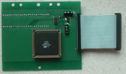
There are probably negative implications to this approach, so I can't exactly recommend it. But, it proves that there shouldn't be a hardware reason the card wouldn't work in the Tandy 1110HD. (Note: The adapter cable for this is also a pain and and a half to build, the XTA2SD and the main board use a different pitch connector so I had to use the smaller pitch ribbon cable, split it conductor by conductor on one end and attach it to the larger connecter one by one. It worked, but you'll need a steady hand, or an adapter board of some kind.)

Great job done, up to now I had no chance to test the XTA2SD on a Tandy 1110, due no chance to get one.
Many thanks that you send me a machine for testing. I really look forward to it for doing the tests and any modification to run the XTA2SD also on a Tandy 1110.

I'm thinking also of designing a special XTA2SD for the Tandy1110 which will fit 1:1 and also have the small ribbon cable connector.
It shouldn’t be hard to add a second set of pins for the 44pin connector. The board is almost perfectly sized to fit in the same location as the Conner drive. Worst case, tightening the spacing between the support chips a little should give you just enough room to add a second pin header to the existing board design. Either that or a small adapter board with a 40pin female connector, power jumper, and the 44pin pin header at a right angle could do it.

And glad to be of service where I can on the spare Tandy machine. I was lucky finding a second one in such good condition.
 
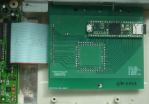
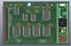
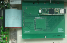
This is the newest XTA2SD design/version for the Tandy 1110. It does replace the HDD drive and will be connected with the original ribbon cable and does fit on the HDD place.

Standard is the replacement for the 20 MB HDD, but with minor changes of the drive parameters of the Tandy BIOS it can emulate a 112 MB HDD.

Due to software swapping in total 16 drives can be emulated.

Thanks arlaneenalra for sending me the Tandy 1110 for testing.

1719842140705.png1719842185979.png
 
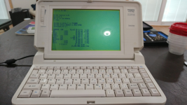
1720555565574.pngIt lives!
I was finally able to address the cabling issues after CallinElvis got me new firmware.

The problem I had was simply getting something that would fit in the case, with everything closed up. The cables that I had were under too much stress after everything was closed up and would lose connection.

Sadly, the original hard drive that I got, which was working, started having problems. So I'm glad I got the XTA2SD working.
 
View attachment 1282699It lives!
I was finally able to address the cabling issues after CallinElvis got me new firmware.

The problem I had was simply getting something that would fit in the case, with everything closed up. The cables that I had were under too much stress after everything was closed up and would lose connection.

Sadly, the original hard drive that I got, which was working, started having problems. So I'm glad I got the XTA2SD working.
NICE!!! Callin does great work with that hardware! I've been playing round with one of the earlier models and have been quite happy with it. I need to do some more testing but I might have a way to get a larger image working without burning a new ROM chip on that machine. I'm pretty sure that you can just replace the pointer to the hdd data table in memory at 0000:0104 and have it point to a new set of values. In theory an "active" boot sector (and possibly a slightly more memory efficient TSR to run after booting) would allow at least up to 112mb drive images to be used. I've had it working with a patched ROM, so I know updating the table works, and an earlier form of the boot sector works too. But that's nasty to play with. It would be Tandy 1110HD specific though. I you know C/Asm you can glance at my rather inelegant code in https://github.com/arlaneenalra/xta2sd-active-boot/pull/1 .. (way too much print statement debugging..). (Pre alpha right now so I would not recommend trying to use it just yet.)

Chris S.
 
Might be a little off-topic, if so my apologies.

Over the last week I have become interested in these XTA drives, specifically how to program them. I possibly would like to interface one to an Atari ST (possibly the printer port).

So I have been searching for information as to how to write code to use the 4 registers, and other technical details.

Back around Y2K I did play with interfacing an (AT-class) IDE drive to an 8051, and thanks to information by PRJC, it wasn't too difficult. I only connected 8 of the 16 databits, as I could afford to lose half the sector.

Since this project appears to have emulated the hardware of an XTA drive, the protocol of register accesses must be known?

At a recent computer faire at the Computer History Museum in Cambridge England, I picked up a 8-bit ISA hard card and was given a "spare" drive. I took the hard card apart and there is a simple PCB with option ROM and buffers. I figured out that the Seagate WD93034 and the spare a Connor CP30104H are both XTA drives. I did play with the card card before disassembling it in my Hyundai 8088 PC, but it didn't appear to work (Seagate drive). I now believe that it might have been caused by unhappiness with my Universal BIOS option ROM, IDK.

The Hyundai PC came with a 8-bit length ISA MFM card and MFM drive. It sort of works, that is if I boot off a floppy I can do a dir of C: , go into and out of directories, and execute some files, but I do hear read retry seeks and at some point it will hang. I am pretty sure that this drive uses the same electronics as became embedded in the early XTA drives.

I searched for any DOS utilities that might allow sectors to be read and displayed, ideally using register access rather than INT13, but I found nothing at all. I wanted to see whether I could figure out what was wrong with the partially working MFM drive.

So I dumped the BIOS "WD1002S-WX2 Winchester Disk Controller BIOS (62-000042-012)" of this ISA card and I started to disassemble the binary using IDA Pro Free. I am pretty sure this is well trodden path :) .

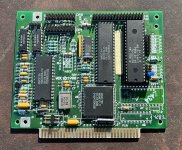
The card is a Western Digital WDXT-Gen2 Plus and I did find some instructions on the web, which included details about jumper settings.

WDXT-Gen2 Plus.JPG

I also found a scan someone did of the genuine Western Digital XTA option ROM source code. My option ROM code shares many similarities, but is more complicated, and appears to use more of the jumper settings, read at address 0x322, to adjust operation in ways I haven't yet figured out. I played with various settings today, here are the results:-

HA9-HA2 HA1 HAO READ PORT WRITE PORT

X - X 0 0 Read data Write data

X - X 0 1 Hardware status Hardware reset

X - X 1 0 Drive configuration Drive select

7 6 5 4 3 2 1 0
W28 W27 W26 W25 W20 W19 W18 W17 <- corresponding jumper name
| | | | | | | |
| | | | | | |____|____ drive0 type 0x03
| | | | |____|______________ drive1 type 0x0C
| | | |
| | |____|________________________ used in option ROM 0x30
| |
| |__________________________________ IRQ5 = 0 / IRQ2 = 1 0x40
|
|_______________________________________ used in option ROM 0x80

X - X 1 1 NOT USED DMA and interrupt control


Two other jumpers (W22 and W21) change ROM address and IO port address, default being C800:0000 and 0x320-0x323.

There are 8 drive tables in the ROM, 4 if the ROM is located at 0xc800:0 and 4 more (different) if the ROM is located elsewhere.

Compared with a later AT-class IDE drive, the protocol appears more complicated, with commands being sent to the drive as a 6 byte packet. Thankfully the Western Digital source code is a major help as there are DEFINES for each command.

Before I dive deeper, has the information to operate the drive using register accesses being documented anywhere?

I'd rather not re-invent the wheel. As much as I enjoy reverse engineering it is rather time consuming. As mentioned in order to make the XTA drive emulators, someone has figured it out, however they might have not shared the information thinking no-one was interested.

Of course the interesting thing is that the electronics shown above on the MFM controller ISA card, became integrated with the MFM electronics on the drive, to give us the first XTA "Integrated Drive Electronics" hard disk drives. So much silicon needed to decode a serial bit-stream :) .

regards...

FWIW1, I also picked up a 16 bit full length IBM AT floppy and hard disk controller card. Looking at the code in the AT BIOS, this card has the standard 8 registers, we all know and love from the AT-class IDE standard.
 
Might be a little off-topic, if so my apologies.

Over the last week I have become interested in these XTA drives, specifically how to program them. I possibly would like to interface one to an Atari ST (possibly the printer port).

So I have been searching for information as to how to write code to use the 4 registers, and other technical details.

Back around Y2K I did play with interfacing an (AT-class) IDE drive to an 8051, and thanks to information by PRJC, it wasn't too difficult. I only connected 8 of the 16 databits, as I could afford to lose half the sector.

Since this project appears to have emulated the hardware of an XTA drive, the protocol of register accesses must be known?

At a recent computer faire at the Computer History Museum in Cambridge England, I picked up a 8-bit ISA hard card and was given a "spare" drive. I took the hard card apart and there is a simple PCB with option ROM and buffers. I figured out that the Seagate WD93034 and the spare a Connor CP30104H are both XTA drives. I did play with the card card before disassembling it in my Hyundai 8088 PC, but it didn't appear to work (Seagate drive). I now believe that it might have been caused by unhappiness with my Universal BIOS option ROM, IDK.

The Hyundai PC came with a 8-bit length ISA MFM card and MFM drive. It sort of works, that is if I boot off a floppy I can do a dir of C: , go into and out of directories, and execute some files, but I do hear read retry seeks and at some point it will hang. I am pretty sure that this drive uses the same electronics as became embedded in the early XTA drives.

I searched for any DOS utilities that might allow sectors to be read and displayed, ideally using register access rather than INT13, but I found nothing at all. I wanted to see whether I could figure out what was wrong with the partially working MFM drive.

So I dumped the BIOS "WD1002S-WX2 Winchester Disk Controller BIOS (62-000042-012)" of this ISA card and I started to disassemble the binary using IDA Pro Free. I am pretty sure this is well trodden path :) .

The card is a Western Digital WDXT-Gen2 Plus and I did find some instructions on the web, which included details about jumper settings.

View attachment 1284821

I also found a scan someone did of the genuine Western Digital XTA option ROM source code. My option ROM code shares many similarities, but is more complicated, and appears to use more of the jumper settings, read at address 0x322, to adjust operation in ways I haven't yet figured out. I played with various settings today, here are the results:-

HA9-HA2 HA1 HAO READ PORT WRITE PORT

X - X 0 0 Read data Write data

X - X 0 1 Hardware status Hardware reset

X - X 1 0 Drive configuration Drive select

7 6 5 4 3 2 1 0
W28 W27 W26 W25 W20 W19 W18 W17 <- corresponding jumper name
| | | | | | | |
| | | | | | |____|____ drive0 type 0x03
| | | | |____|______________ drive1 type 0x0C
| | | |
| | |____|________________________ used in option ROM 0x30
| |
| |__________________________________ IRQ5 = 0 / IRQ2 = 1 0x40
|
|_______________________________________ used in option ROM 0x80


X - X 1 1 NOT USED DMA and interrupt control

Two other jumpers (W22 and W21) change ROM address and IO port address, default being C800:0000 and 0x320-0x323.

There are 8 drive tables in the ROM, 4 if the ROM is located at 0xc800:0 and 4 more (different) if the ROM is located elsewhere.

Compared with a later AT-class IDE drive, the protocol appears more complicated, with commands being sent to the drive as a 6 byte packet. Thankfully the Western Digital source code is a major help as there are DEFINES for each command.

Before I dive deeper, has the information to operate the drive using register accesses being documented anywhere?

I'd rather not re-invent the wheel. As much as I enjoy reverse engineering it is rather time consuming. As mentioned in order to make the XTA drive emulators, someone has figured it out, however they might have not shared the information thinking no-one was interested.

Of course the interesting thing is that the electronics shown above on the MFM controller ISA card, became integrated with the MFM electronics on the drive, to give us the first XTA "Integrated Drive Electronics" hard disk drives. So much silicon needed to decode a serial bit-stream :) .

regards...

FWIW1, I also picked up a 16 bit full length IBM AT floppy and hard disk controller card. Looking at the code in the AT BIOS, this card has the standard 8 registers, we all know and love from the AT-class IDE standard.
There's some information in the datasheets for the controller ICs
* Cirrus Logic CL-SH260 : http://bitsavers.trailing-edge.com/...Enhanced_PC_XT-AT_Disk_Controller_Jan1991.pdf (for the Connor CP-2024)
There's also some information in PC XT Technical Reference Manual http://bitsavers.informatik.uni-stu...t/1502237_PC_XT_Technical_Reference_Apr83.pdf Check out around page I-179.

Most of what I've seen doesn't talk about the ordering of the commands though. Just what the individual commands are. There's also a Western Digital controller IC reference floating around but I don't have the link immediately handy.

If you have a BIOS that actually initializes the drive, you might be able to work backwards from there for a specific subset or a logic analyzer attached to the XTA bus to catch the flow of commands. If you look back through this thread, I think that's been done but I'm not sure if anyone has published those results.

Based on my read of the Cirrus Logic datasheet, the controller chip mostly handles negotiations with the host system while an attached micro controller actually manipulates the drive and responds to commands, so while the datasheet is valuable, it doesn't help too much in actually controlling a drive. My understanding is that the MFM command set is supposed to be very close to the XTA one ..
 
Last edited:
Atari STs have an SASI (predecessor the SCSI) hard drive port built-in, so wouldn't it be easier to use that?
Well yes, but if you look at the schematic for the Atari hard disk drive, to convert to a SCSI interface, it is quite complicated. Nevertheless the schematic and software and information is all now "out there" for anyone who wants to try to build their own.

For ease of getting a hard disk replacement, there is a commercial solution which uses a SD card (UltraSATAN), and then a public domain "blue pill" solution.

My project to connect the XTA to the Atari was for fun, a bit of a challenge. So my project/idea might be nuts and make no sense to anyone else :) .

Unfortunately I have to scrap the idea anyway. After more testing today I found that the Western Digital XTA drive from the filecard is broken. I was able to low level format and fdisk, but DOS format fails. The replacement Connor drive also did not work when connected to the ISA card from the filecard. When I googled I found that it was not after all XTA (which is what I was told when I got it). So I do not have a working XTA drive to even experiment with.

Back in the 80's I had a custom interface from the DMA port to a MFM hard disk drive, but using it in a non-standard way. It did work, but might have been slow. Nevertheless a friend used this solution for his Atari based BBS for many years. I still have that MFM HDD and it might have some software that I would like to recover. Part of the reason of looking into this XTA interface, is that it is the same protocol as used by the MFM controller ISA card, and I initially was hoping to dump the Atari MFM drive while connected to the old 8088 PC via the ISA MFM controller.

I will give the IDA Pro disassembly a few more days to try to understand how to send commands to the drive. I was going to write some code using Turbo-C to do this. If I get anything working I will post here for any interested parties.

I have 4 "MFM/XTA" cards. I will dump the ROMs and post the binaries somewhere (minuszerodegrees?).
 
Back in the 80's I had a custom interface from the DMA port to a MFM hard disk drive, but using it in a non-standard way. It did work, but might have been slow. Nevertheless a friend used this solution for his Atari based BBS for many years. I still have that MFM HDD and it might have some software that I would like to recover. Part of the reason of looking into this XTA interface, is that it is the same protocol as used by the MFM controller ISA card, and I initially was hoping to dump the Atari MFM drive while connected to the old 8088 PC via the ISA MFM controller.

Usagi Electric (with AJ from Forgotten Machines) had a video on imaging MFM hard drives a while back. The emulator they were using was a bit on the expensive side though. I'm pretty sure AJ was at one of the VCF conferences imaging drive, though I have no clue if that will happen again. If you can find someone with that gear, it might be an option to pull the data off the drive.
 
I think that further back in this thread there was a question about where the drive parameters (cylinders, heads, etc) came from to initialise the drive.

The MFM drive in my Hyundai 8088 PC was on its last legs and could just about do one dir before locking up the PC.
The 8-bit ISA MFM controller understands the XTA standard interface with its 4 register interface, normally at I/O address 0x320.
From the same junk faire in Cambridge I got an Imprimis 30Mb MFM hard disk.
I connected it up, low level formatted with g=C800:5, fdisk'ed, high level formatted and managed to install Hyundai DOS 3.21 . It booted into DOS OK. I worked like a charm. Wow a working 30Mb MFM drive, that must be worth a pretty penny on Ebay :) .

What has puzzled me, is that the drive is 30Mb. I have been disassembling the option ROM code. There are 4 drive parameter tables if the card is found at the standard location of 0xc800:0, with the choice determined by 2 jumpers (see my previous post). If the ROM is at a different address (there are 3 possible alternate locations with corresponding alternate I/O addresses), there is a second drive parameter table again with 4 entries, with the choice determined by a different 2 jumpers.

Non of the drive parameter tables matches the Imprimis (5 heads, 989 cylinders), nevertheless it appears to work. The park utility says it is moving the heads to track 989, which is the correct number of tracks.

So does the Imprimis or perhaps the ISA card chipset have some EEPROM in which the programmed cylinders and heads are stored?

Why aren't they overwritten when the ROM code sends the OP_INIIT_DRV_PARM command when doing an INT13,0 (disk reset) command to setup with one of the sets of values from the table?

Just FYI, I have been playing with accessing the drive at the I/O port level, with some code written in Turbo-C. I did write incorrect values using the "INIT_DRV_PARM" opcode. The drive then no longer booted into DOS. So the incorrect values which I wrote while playing around appear to have "stuck". My assumption before all this experimentation was that the drive (Western Digital controller ICs) would need to always be told the number of heads and cylinders in order for them to do the right thing every time, and certainly after a power cycle.
 
So the incorrect values which I wrote while playing around appear to have "stuck". My assumption before all this experimentation was that the drive (Western Digital controller ICs) would need to always be told the number of heads and cylinders in order for them to do the right thing every time, and certainly after a power cycle.

There are a number of ways that the controller could store that information. One possible technique is to write it to a hidden cylinder at the start of the drive. (Context: https://minuszerodegrees.net/5160/hdd/hdd_xt_controller_categories.htm which I shamelessly snagged from https://forum.vcfed.org/index.php?threads/mfm-drives-in-at-machines.72535/post-878262 because I wanted to have a reference).
 
Back
Top