clh333
Veteran Member
Long story shortened: After finding a copy of the E&L "Bugbook" I found an LD-1 "Pencilbox Logic Designer", which the book references, on eBay. The nominal voltage for power input is +5 VDC but looking at the power input section I concluded it was regulated and could accept more voltage - within reason, of course. I plan to power it with a battery of 6 NiMH AA rechargeable cells.
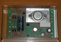
At first glance I thought the TO-220 transistor was a 7805 regulator but it is not; it is a TIP29A, which is typically used for amplification, usually audio. As I understand from a little Internet research this was a common setup in the days preceding the 7805. The LD-1 dates from the '70s; I don't know how long the 7805 has been around.
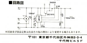
I don't have a schematic but it seems the input regulation is composed of four components: the TIP29A, resistor, diode and Zener. If I understand the theory correctly, the TIP29A is not performing the regulation, however: Its role seems to be current amplification to provide enough current to supply the diode which actually regulates voltage. I'm assuming that's the role of the Zener diode pictured at the left, and the other diode is just for protection against reverse bias.
But this is all just speculation on my part: If anyone can explain it better I'd welcome their input.
Thanks,
-CH-


At first glance I thought the TO-220 transistor was a 7805 regulator but it is not; it is a TIP29A, which is typically used for amplification, usually audio. As I understand from a little Internet research this was a common setup in the days preceding the 7805. The LD-1 dates from the '70s; I don't know how long the 7805 has been around.
I don't have a schematic but it seems the input regulation is composed of four components: the TIP29A, resistor, diode and Zener. If I understand the theory correctly, the TIP29A is not performing the regulation, however: Its role seems to be current amplification to provide enough current to supply the diode which actually regulates voltage. I'm assuming that's the role of the Zener diode pictured at the left, and the other diode is just for protection against reverse bias.
But this is all just speculation on my part: If anyone can explain it better I'd welcome their input.
Thanks,
-CH-