• Please review our updated Terms and Rules here

Acorn atom

Gary C

Veteran Member
Joined
May 26, 2018
Messages
2,645
Location
Lancashire, UK
Time to get the Acorn Atom on the road

New key donated (thank you every so much !) so keyboard stripped down to find a second key stem snapped along with the missing key.

Also looking at the (already snapped) keystem on the missing key, it doesn't match the others. It fits but is looser and once of the coils of the Sabre Coil switch is not round and sticking in the housing.
So managed to get the faulty coil contact to sit in the depressed position so that the second can swing and make contact. Printed a connector and glued that in place and now have stems on all keys ready for refitting.

But first power up.

Transformer giving out 9v, yay, then 0V, boo now 12V. Turning the transformer upside down and it gives out 12v, turn it right way up, nothing. Annoyingly the case is riveted shut requiring careful snipping out (cant drill, they just spin). Need to find replacements

Transformer exposed and failed solder joint on a 'thingy' located. Not sure what it is. Silver tube with a black cone end :)
 
Powered up and screen barely shown on TV.

Well, blow me. The Acorn Atom puts out a 60hz signal ! a British computer putting out a vaguely NTSC signal. Solder in a header for the composite video and stable screen.

However the prompt is

AAORN AAOM
>>

Which doesn't quite look right.

Then it failed. Give it some time and up it comes only to fail after about a minute. Probably something getting hot.

Odd thing. Press and hold reset and the CPU reset line goes low, but activity turns up on the buss ? That then vanishes when reset is let go.
 
I liked the fault with the transformer 😉!

That must have kept you amused for a while...

It reminded me of a fault with a PET. With the lid open it worked. With the lid closed it didn't work. It turned out to be a light sensitive EPROM (without a label on the window).

The 6847 Video Display Generator (VDG) doesn't appear to have a reset, but I suspect it performs its own DMA.

Dave
 
Last edited:
Interestingly, one line I occasionally see activity on, when reset is depressed, is the VDG line which is used to put the 6847 into trisate when the CPU wants to write to the video memory, however this line is generated from Phase 2 of the CPU and address lines A12 to A15 only which should be static with reset pressed.

The VDG should just run by the looks.
 
Seriously confuzed. Power up from cold and I get a screen and can type (its not always perfect but its there). Monitoring the video RAM address bus generated from the VDG, I can see it getting more and more flickery until it stops.
Seems that the 6847 is crashing as it gets warm, fair enough and a spare on order.

However, I can't understand how the address bus directly on the 6502 sometimes shows activity while reset is asserted.

Odd
 
Its been niggling me that when the 6847 shuts down, the 6502's bus is affected and the signal from the uP to the VDP to stop reading the memory while it writes to it, also vanishes.

The busses are separated by a couple of 81LS95 and its noticeable that the higher address lines appear to die when the VDP stops working. A symptom or a cause ?

IC27 deals with buffering the higher address lines between the uP and the VDP so if thats overheating and pulling them down, it would mess up both of them. IC27 removed and now even after the warm up, a stable (but full of crap as the CPU cant write to it) display and more notably, the VDG line remains active when you press a key.

No spares but hopefully the fix.
 
Good thinking.

I think there is an SN74... equivalent for these buffers isn't there?

I remember that from my NASCOM and Sinclair MK14.

Dave
 
Step forward *error no it isn't

New 81LS95 fitted and even after 10 minutes, the display is 'stable' and updating. I say 'stable' however because there is still an issue in that when started, it displays

AAOONNAAOO
>>

and every keypress gives two characters on screen and there is quite a bit of 'snow' so its possible the data buffer is also giving problems.

ATOMIC_TESTING program is also under development and just remembered how to loop through a 16 bit address without 16 bit registers (so much easier with a Z80) using indirect addressing, so with any luck I should have an accompanying test rom soon.

Damn, after 15 minutes, same corruption and crashing of the 6847 and the 6502. Will wait until the new VDG gets here for the next update.

Though I had it then.
 
Last edited:
AAOONNAAOO

looks like:

ACORN ATOM

But with the first character of a pair duplicated into the second character position.

If this was a Commodore PET, I would say that the ODD latch accidentally stored the same character as the EVEN latch did...

Dave
 
I think I might have two problems.

There is something clashing between the two data/address busses, when they are separate, both processors run fine but with the buffers installed it goes wrong. Need to investigate the select signals but they seem simple and operational. Possibly one with a slow response.

I assumed that it was the address buffers, but of course it could be the data buffer but its hard to test as it crashes with it in after a few minutes. Probably have to just try a new IC.
 
Last edited:
Of course. Just need to install ic with all the legs on the cpu side out of the socket and see if they show activity as it warms up
 
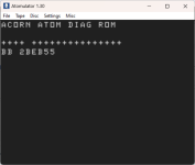
While waiting for new chips, diag rom is coming along. Atomulator is perfect for testing code without having to mess about blowing an EPROM
Could do with lots of prettifying. The BB is the read in error, then the address of the error then the 55 is what it was expecting. For each 256K tested, it puts a + on the screen so for a working machine, the line of +'s strobes across the screen.
But it 'works'
The PIA test needs a scope and so does the page 0 test as it assumes the display will probably not work at first.


1730272870937.png

ASM80 is odd though. Use an .ORG and setup the reset vector, then .ORG to the start of the Kernal ROM, but when the HEX file is turned into a binary file with Hex2Bin, it runs from 0 to the top of the code but misses out the reset vector meaning I need to go into the binary file, add the vector then delete all the data from 0000 to FC00. Odd
 
Last edited:
Data bus buffer replaced and screen still has the double character but seems more stable, however the buffer is getting hot so not sure if its a symptom rather than the cause, so more investigation required.

Also, noted that pin 23 which is address A1 of the VDG is a nice and healthy square wave, but at the ram its vanished. Pin 23 of the socket has no contact top to bottom and looks corroded.

Its obvious this Atom was assembled from a kit as the soldering is quite poor and I have no idea what flux the solder was cored with. Its almost like a thick tar as its heated for desoldering. Going to need quite a bit of flux and take this one slowly to try and prevent damage to the board. Take it slowly and clean it up before fitting the new socket.
 
40 Pin socket removed with no damage, used a lower temperature than I normally use (set it at 250C) as the solder seemed to melt easily. Some of the old flux though is hard and like lacquer. So much so, its likely to cause some damage trying to remove it all, so cleaned up as best I can. The pads are nice and shiny though.

New socket soldered in (and looking much better than the one that was removed) and . . .

Yay, now have the full ACORN ATOM message rather than AAOONNAAOO

Still need to do a duration test as the data buffer is still getting a bit warm.
 
Yes, asm80 is a bit weird. I have also broken it a couple of times with valid assembly code.

I have found a slighter better online assembler for Z80 code that I haven't managed to break (yet)...

However, asm80 is quite nice in that it supports multiple CPUs and a basic emulator runtime environment.

Dave
 
Nope not fixed.

So, further investigation and the machine does something odd before it fails in that writing to the screen becomes really slow. Pressing reset and each character of the startup message takes about 1/2 second to display.
Now looking at the kernel code, the display routine waits for notFS before it updates while my DiagROM doesn't care and happily updates the screen. This comes from pin 37 of the 6847 and through the 8255 port C bit 7.

When I use my diagROM which steps through all 8255 ports in output mode to test and thus cycles the 6847 through each mode, I can see FS appearing and disappearing as modes are changed. Looking at the datasheet, FS is generated from the end of the display window until the next vertical sync, so it should be present all the time regardless so it looks as if its the 6847.

The diagROM also tests all the VDU memory and its never thrown up a fault suggesting its not a buffer fault, but its odd that removing them keeps the machine running

Still waiting the spare, didn't turn up and case opened. Think I will use Cricklewood more often as they might charge a little more but have cheap 1-2 day delivery.
 
Confused to say the least.

New 6847 put in and no change.

The 6847 puts out Field sync to indicate that the VDU can be updated. This pulse is meant to go low at the end of the last line until the next vertical sync pulse. At powerup this pulse is correct and all is well but after a while, this pulse shrinks to a tiny fraction of the size it should be. This limits the time the CPU can update the screen and things crawl. Now the 6847 isn't 'programmable' like the 6845 is, it just changes mode based on several inputs so I'm really not sure whats going on here.

Thinking, must check the voltage is in spec . . .
 
Everything looks right except the failure of the Field Sync

Ah damn. At least I fixed the washing machine today.
 
Back
Top