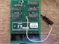
Persistence pays off... there is a review of the Turbo Board in Profiles v2n5 issue (page 51). Here is a portion of the review that goes over installation--looks like pin 8 of u67 must be cut or pulled away. I am guessing the clip goes to pin 5 of U86 for the 5 MHz clock (the article doesn't specify).
Once inside the computer, use the installation
sheet's photos to determine the location of the chips
involved. Next remove the Z80 chip. This is done by
prying the chip from its socket with a small screw-
driver. I was a little nervous about this, but it did
seem to come out fairly easily. One has to be sure not
to bend the chip's pins.
Next, locate the chip marked U67 so that you can
remove it and bend pin 8 away from contact with the
circuit board. Unfortunately my U67 chip was sol-
dered to the motherboard. The instruction sheet
goes on to say that "If the chip is soldered into the
circuit board, it must be desoldered, removed from
the board and a socket installed in its place. Then
the chip is to be reinstalled per the earlier instruc-
tions." (I think we just stepped beyond the abilities
of the non-technical user, which includes yours
truly.)
There's an easier way than desoldering the chip.
The instructions say you can try to cut the pin on
the chip while it's still soldered to the board. The
problem is that the chip is crowded, leaving little
room to get a tool in there. I tried my electrical dikes
which were too big. However, the dikes did manage
to scrape some of the pin's metal off on each suc-
cessive snip. After about ten snips, the pin parted
and I was able to gently bend the remainder away.
The next step is installing the Turboboard into
the Z80 socket. This went easily. To finish the
installation, attach one jumper clip to a chip pin
(easy) and fasten the 2.5MHz-5MHz switch next to
the reset button (also easy).
Apart from the minor snags, the installation is
easy and the instructions are complete. Remember
to disconnect power from your computer before you
open it up. Before you make this modification, look
to see if your U67 chip was socketed or soldered in. If
it's soldered, purchase a (very small) set of wire snips
to clip pin 8.
Replace the cover and power cord, and you're
done. The whole installation took about thirty min-
utes (which includes my searching for my electrical
dikes).


