• Please review our updated Terms and Rules here

Anyone recognize this clock?

falter

Veteran Member
Joined
Jan 22, 2011
Messages
6,580
Location
Vancouver, BC
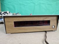
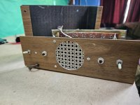
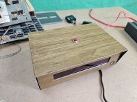
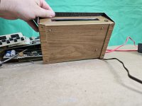
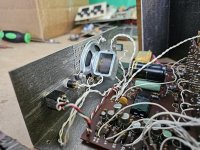
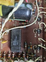
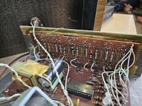
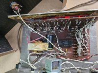
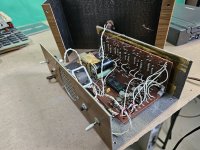
Picked this up for next to nothing. I frequently run across these old clock projects in various electronics magazines and I'm 99% sure this probably is a magazine project although no idea whose it is. Some of the wires to the LED board have broken off .. Definitely needs a bit of TLC. Looks to have been built around 1975 and the boards have silkscreening so I'm assuming they were offered as a kit.
 

Attachments

  • 20231030_160836.jpg
    20231030_160836.jpg
    3.6 MB · Views: 33
  • 20231030_160805.jpg
    20231030_160805.jpg
    3.4 MB · Views: 32
  • 20231030_160841.jpg
    20231030_160841.jpg
    3.5 MB · Views: 29
  • 20231030_160847.jpg
    20231030_160847.jpg
    3.7 MB · Views: 33
  • 20231030_160801.jpg
    20231030_160801.jpg
    3.6 MB · Views: 36
  • 20231030_160753.jpg
    20231030_160753.jpg
    1.7 MB · Views: 38
  • 20231030_160733.jpg
    20231030_160733.jpg
    4 MB · Views: 36
  • 20231030_160730.jpg
    20231030_160730.jpg
    4.3 MB · Views: 33
  • 20231030_160728.jpg
    20231030_160728.jpg
    3.6 MB · Views: 36
That thing is home made. So if you are asking if anyone recognizes it do you mean do they recognize THAT EXACT ONE? Thats.. Well thats something. I like someone who says to themselves.. You know what I am just going to make my own digital clock.....

In truth maybe the original plastic housing was smashed so they made a new one. Just some speculation.
 
I had a similar clock. It is difficult to figure out which kit was used without a clear image of the main board. Someone with a lot of time could go through the dozens of kits and find a match. The main board has labels for all the components which is a sign of being a kit with the case and the inserted speaker and buttons placement would have been designed by the builder.

https://electronicsusa.com/clockmuseum.html has several kits and the designs aren't all the different.
 
Yeah I didn't think it likely it'd be instantly recognizable. There were literally dozens of these projects in magazines. I'll have to get the PCB out and see what I can find. Maybe the chip used will help. The LED board appears to have a part number on it.. but who knows if these came together.
 
I started working on this clock today and managed to get it to run (thanks to a youtube video on a clock using a similar chip that featured a datasheet with a handwritten note that hour and minute set must be pressed together to start it). The clock part seems to work fine, however the display LEDs are missing segments.


I'm trying to understand how this works, I *think* from what I've read I'm dealing with dead segments in the LEDs themselves?
 
The old 7 segment LEDs were often over-driven and did develop dead segments after a time. I've got a few oldies that exhibit that behavior. However, the MK50252 appears to belong the the MK50250 family described on PDF page 119 here.
It has long been out of production and isn't even listed in the databooks as such.
 
Surely there is a way to light up all the segments at once to do a "test" of all segments to spot dead ones?
 
I started working on this clock today and managed to get it to run (thanks to a youtube video on a clock using a similar chip that featured a datasheet with a handwritten note that hour and minute set must be pressed together to start it). The clock part seems to work fine, however the display LEDs are missing segments.


I'm trying to understand how this works, I *think* from what I've read I'm dealing with dead segments in the LEDs themselves?
you could have driver issues. I see one segment that never lights up on any digit (segment F)
 
There is a schematic in here: https://www.worldradiohistory.com/Archive-Radio-Electronics/70s/1976/Radio-Electronics-1976-11.pdf.

The display is multiplexed - so you have independent digit and segment drivers.

It looks like the driver ICs (from the article) have been replaced by discrete transistors - so could just be a bust segment driver transistor.

The datasheet for the MK50250 is here: https://datasheetspdf.com/pdf-file/941733/MOSTEK/MK50250/1.

You can see the segment and digit drives here (hopefully the 50252 is very similar to the 50250). You could scope all of the pins and see which ones don't do anything! Compare these to the datasheet.

Dave
 
Many thanks gents.

This clock is really, really fragile. I had two wires pop and pull traces off as they did it, and the confines are really tight. Is there a simple way to trigger or jumper a suspect segment and see if it lights? I'm afraid this thing is going to crumble on me if I get much more aggressive. I'm thinking about recreating the LED panel at minimum here as it just seems to be very cheaply made the copper wants to fall off.
 
The problem is that the multiplexing also (effectively) limits the current (or more correctly power dissipation) in each LED segment.

Bypassing something with a piece of wire could result in damage.

Bypassing something with a resistor would be better still.

Probing with an oscilloscope will still be best.

Dave
 
Okay. I think i'll try very gingerly to remove everything here and then I can more easily get probes on it.
 
Back
Top