• Please review our updated Terms and Rules here

Apple IIc Monitor Tube displaying strange behavior

You can replace these glass passivated diodes with the 4A rated BY448. If you strike one with particularly thick lead wires, use a BY228 that has a 5A rating. Both of these are over 1600V piv rated and have fast switching times, they are probably far superior to the diode that was in there in the first place and they are easy to get.

Thanks Hugo, I will make an order for a set of both when I get home.
 
Ok, I know its been along time but I have an update. I spent the majority of the day working on the two faulty IIc monitors. First off Thanks again Hugo for recommending those diodes.

So the board with the missing and crumbling diodes; I replaced them all with the ones mentioned above. Voila! one Board, Psu-board and CRT now work perfectly! I decided to just replace the same diodes on the other board just because it may be a failure point ( I have never really seen diodes be a failure point but after dealing with these IIC monitors its possible).

After doing so I tried the known good CRT monitor with the secondboard and second psu-board. Got display but much like mentioned early in the post. I decided to just try the second board but use the psu-board from the first working machine. Then I realized the second board was working great as well! The problem is with the psu-board. The caps were replaced a couple months back. That only leaves the transformer (which I cannot find any part numbers for in the case it may be bad) and two transistors (2SC1213C and 2SA673C) which I already put an order for replacements. If its not either transistor Could it be the transformer? The display comes in an out of vertical hold and there are waves just rippling through the image.

Now lets talk the second CRT. I know we were talking about the internal grid being a possible problem and maybe turning the yoke. Honestly I never got to that. I did try the CRT on the known good board and PSU and it gets a steady display although quite small. Even with adjusting all the pots the image squished. I guess I will measure resistance in the yoke next as well.

looking in Sams computer facts I see the power transformer is labeled 2869-239-0104 by PELCO but I cant seem to find anything online about it.
 
Last edited:
Compare the resistance of the joke windings between the bad and the good tube. The "squashed image" tube has probably shorted turns in one deflection coil. The good news is that probably you can rewind the bad yoke if it's the vertical windings that went shorted.
If the other fault is in the power transformer, just measure the output(s) of the good one and find a similar replacement. You will find the same transformer probably only on another IIc monitor.
Frank
 
Ok so the horizontal winding on my good CRT reads 0.49 Ohms, Horizontal on the Bad CRT is 0.57 Ohms

Vertical winding on the Good CRT is 2.19 Ohms, and on the Bad CRT is 4.24 Ohms. That is a pretty big difference on the Vertical winding on the bad CRT right?
 
Ok so the horizontal winding on my good CRT reads 0.49 Ohms, Horizontal on the Bad CRT is 0.57 Ohms

Vertical winding on the Good CRT is 2.19 Ohms, and on the Bad CRT is 4.24 Ohms. That is a pretty big difference on the Vertical winding on the bad CRT right?

That is unusual. Often (for many monitors) the two vertical deflection coils on the yoke are wired in series so as to gain as much overall inductance as possible (I would have to look at the monitor schematic again) therefore, in a fault condition like shorted turns, the resistance of the faulty vertical coil pair should be lower than normal. I will have to check the schematic which I do not have on hand. If it was a scenario in this particular monitor design where the two vertical coils were originally wired in parallel, and one went open circuit, it could explain why you are seeing about double the resistance on the faulty coil compared to a good yoke. Check the solder connections, from the vertical yoke windings, of the enameled copper wire to each terminal on the yoke.
 
I dont know. There was some black gook on the coil. I wasnt sure if there was corrosion. I sprayed some deoxit on it. (after I took the readings; made no difference of course)

Solder connections look fine. I guess I can try reflowing them when I get the replacement transistors in.
 
I dont know. There was some black gook on the coil. I wasnt sure if there was corrosion. I sprayed some deoxit on it. (after I took the readings; made no difference of course)

Solder connections look fine. I guess I can try reflowing them when I get the replacement transistors in.

check very closely on all the enameled copper wiring that is visible on the yoke, for a broken wire, perhaps one under tension, or a physical impact area on the yoke that might have damaged a wire.
 
I gave it a look over and examined the copper wires from the solder connections back. Nothing obvious jumped out at me. I suppose I can post some pictures tomorrow.
 
Ok so the horizontal winding on my good CRT reads 0.49 Ohms, Horizontal on the Bad CRT is 0.57 Ohms

Vertical winding on the Good CRT is 2.19 Ohms, and on the Bad CRT is 4.24 Ohms. That is a pretty big difference on the Vertical winding on the bad CRT right?

unusual... looks like the vertical coils are wired in parallel and you're missing one coil on the bad CRT's joke.
I would unsolder both coils from the wiring posts on the bad joke and measure the resistance separately on both windings, one should be open or not making good contact in the current solder joints.
Frank IZ8DWF
 
Something is very wrong here. I found the Apple IIc circuit.

As is usual, the V coils are wired in series and the H coils are in parallel.

So it is not possible via any scenario I can see that your faulty yoke measures twice the resistance of the good one. You must have got them mixed up and the faulty one is half the resistance of the good one (as we first suspected).

So likely the bad one is 2.19 Ohms, and on the good is 4.24 Ohms.

Please double check this.

The schematic states that the resistance (across the yoke terminals) for the vertical coils is 6.5 Ohms and for the H coils is 0.3 Ohms and the V coils are in series, the H coils in parallel.
 
You must have got them mixed up and the faulty one is half the resistance of the good one (as we first suspected).

So likely the bad one is 2.19 Ohms, and on the good is 4.24 Ohms.

Please double check this.

I didnt mix up the readings, I have the CRTS Labeled (not that I need to, the bad one has a Rusty implosion ring). I just triple checked the readings again to confirm. I will do as IZ8DWF suggests and desolder and test again. But the working CRT has half the resistance. I will check the resistances later today when I have time, in the meanwhile here are some pictures with labels of the CRT's : https://photos.app.goo.gl/svH7NUWsfmAM3sRT7

Please excuse my messy work bench, I'm in the middle of too many projects.

to me it looks like the vertical windings go to yellow/green wires and they indeed look like parallel connected.
Also the ends of a vertical winding seem too darkened on one CRT, I can't tell which one. Might just be dust, but worth checking.

Frank
 
Last edited:
I agree, despite the schematic saying that the vertical coils are series connected, they look in reality parallel connected, and the resistance figure quoted on the schematic is incorrect. So we are back where we were with the faulty yoke having one of its vertical coils open circuit.

De-solder at least one of the vertical coil wires from the tags (on the faulty yoke) and test the continuity of each vertical coil separately. In theory one is open circuit, then concentrate on that particular coil to find why.
 
Iso these Carts use Hitachi tubes. I also have another iic monitor which has a Samsung CRT and everything on the inside of that monitor is much different from these Hitachi screens. I was looking in Sam's computer facts for the iic monitor, they seem to reflect the Samsung screens.. Hugo possibly the figures you quoted were from that series monitor.
 
Iso these Carts use Hitachi tubes. I also have another iic monitor which has a Samsung CRT and everything on the inside of that monitor is much different from these Hitachi screens. I was looking in Sam's computer facts for the iic monitor, they seem to reflect the Samsung screens.. Hugo possibly the figures you quoted were from that series monitor.
I've never trusted too much schematics of that era, monitors' schematics are particularly bad. I had to repair a few CBM 1702 monitors and the actual circuit was not so similar to the one reported in the service manual that can be found on the internet.

Frank IZ8DWF
 
Ok, So I have news. Bad news. After trying What hugo mentioned. I tried a continuity test. One wire wasnt having any continuity (connected to yellow vertical coil) I discovered those dark patches are indeed corrosion, which hide a lighter green corrosion which you know what that means. I found at least 4 breaks in the copper windings. I thought I could repair it, but I kept finding more and more breaks. I guess thats it right? Anyone have a blown IIC picture tube with a good Yoke?
 
Ok, So I have news. Bad news. After trying What hugo mentioned. I tried a continuity test. One wire wasnt having any continuity (connected to yellow vertical coil) I discovered those dark patches are indeed corrosion, which hide a lighter green corrosion which you know what that means. I found at least 4 breaks in the copper windings. I thought I could repair it, but I kept finding more and more breaks. I guess thats it right? Anyone have a blown IIC picture tube with a good Yoke?

I wouldn't be so negative on this one, the vertical coils are not hard to rewind by hand, it takes a bit of time and patience and a good run of wire with suitable diameter. The ferrite half-cones can be separated from the yoke assembly by removing usually a few steel clips. All the windings for vertical deflection are wound around the two half conical ferrites. You need to count the number of turns wound on one ferrite core and rewind the broken one. The start of the winding can be secured in place with a bit of insulating tape.
Frank
 
You make it sound easy. Im not saying I cant, but precision winding probably takes alot of practice. And wouldn't you need some kind of coated copper? And you are basically saying rewind the whole coil as I have to count the first ones windings and copy to the second correct? Have you ever done this ?
 
You make it sound easy. Im not saying I cant, but precision winding probably takes alot of practice. And wouldn't you need some kind of coated copper? And you are basically saying rewind the whole coil as I have to count the first ones windings and copy to the second correct? Have you ever done this ?

Yes, you need enameled copper wire, there's not much "precision" involved, just count the turns and space them evenly (see the spacing on the other half winding) on the "half-funnel"-shaped core. I've rewound vertical coils to convert monitors from raster to vector. There're good informative videos on how to rewind vertical yokes to convert monitors for vector drive. The difference is that when you convert the vertical windings for vector operation you usually need thicker wire than the original one and fewever turns than the original winding. In your case, you have to copy the other half winding as much as possible. Keep pictures of the original winding before removing the old broken wire, that's super important to remember the correct direction for windings.
Frank
 
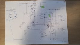
Hello all! Sorry to respawn this old thread but I'm needing some help. I've bought an Apple IIc 9" Monochrome monitor just like this topic models. It was in a very bad shape since it was found in a dumping terrain in São Paulo, Brazil. The seller told me it was not working and took the caution to make a very good shipping box. It came exactly as found. Well, I took it apart using the Adrian's Basement video. Took every single piece apart, make a retr0bright of the case. It's the Hitachi variant and the first thing I noticed was the 4 rectifing diodes on the rectifying bridge totally missing hehe... another diode that seems the same part on the power supply board was broken as well. Changed to 4 x 1N4007 and another 1N4007 on the board. Then the power supply turned on and is giving like +20V on the +B voltage pin. Adjusting the +B trimpot didn't changed.. 19.8 to 20.2V only. When I've pluged the power supply to the analog board, 2 of the 4 rectifying bridges diodes smoked. I've try to find the Hitachi variant schematics with no success. Does anybody have this schematic? Thanks in advance! Attached the power supply board schematic draft I've made by hand...
 

Attachments

  • 1.jpg
    1.jpg
    122.1 KB · Views: 4
Back
Top