• Please review our updated Terms and Rules here

CBM 8032 for repair

Sarnian

Member
Joined
Sep 25, 2024
Messages
39
Location
Guernsey
Hi All

I have been given a CBM 8032 (UK spec) to get running, I'm more of a BBC Micro / Apple-1 person but thought I'd give it a go.
It's in pretty good shape, but after a thorough inspection all a can find apart from a light layer of dust is a blown fuse.
So I have two questions
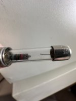
1. Now before I rush off and order a new one from DigiKey would this be the original fuse that came with it? 1/2A 250V 313 3AG
Screenshot 2024-09-25 at 22.18.33.png

If it looks right then I've found this on DigiKey https://www.digikey.co.uk/short/bzv204hc as a replacement.

2. Once I have the new fuse, what should I be testing/doing for before I turn it on?

Thanks
Sarnian

tempImageVDmiQN.jpg
tempImageDdvTbB.pngIMG_9377.JPGIMG_9415.JPGIMG_9383.JPG
 
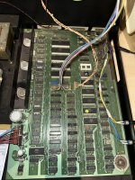
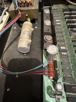
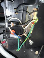
When an old fuse like that fails, there may not be an actual fault, or there might be. I cannot see an RFI filter cap on the incoming line power, so not likely the cause. It could be though that the 23,000F main filter cap has gone leaky and the power up surge current killed the fuse. But given that there is no vaporised metal inside the fuse on its glass wall, you may find the computer springs to life when you replace the fuse.
 
First off (as this is your first post) welcome to VCFED.

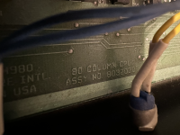
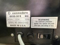
Can you photograph and post the rear panel around where the fuse holder is please? Sometimes they state what the fuse rating should be...

For a 110V supply, the fuse is specified as 1.6 A SLOBLO. For a 230 V supply it should be approximately half of that, or 0.8 A (800 mA) SLOBLO.

0.5 A does seem a little bit low to me, but I will check my 8032 for you after breakfast!

Before powering up, I would disconnect the transformer from the main logic board by pulling the plug out. That will remove most of the load (excluding the monitor) off the transformer and it will disconnect the large external smoothing capacitor.

You can then power up and measure the AC voltages on the secondary of the transformer.

Have you found the schematics online for your 8032? Also, what test equipment have you got.

I would also check that you have a good safety earth connection between mains earth and the case, and that live and neutral are not shorted to the case anywhere. Use a PAT tester [sic] set to 250V isolation test, or a multimeter. Also check (with a multimeter) that the ON/OFF switch works. Safety first...

Dave
 
Last edited:
Hi all

Thanks for all your replies.

Can’t see anything leaking from the filter cap, are they prone to failing?

I have found the schematics but only have a multimeter, will follow your suggestions once I get the correct fuse and test what I can.

IMG_9427.jpegIMG_9428.jpeg
Thanks
Sarnian
 
I checked my 8032 and it does (indeed) have a 0.5A fuse. My PET is even marked (with an original label) as requiring a T0.5A fuse. The 'T' designation indicating a SLOBLO fuse.

That looks to be a very weird fuse! If you also look at the link you provided, those fuses are expensive. I would just nip down to a local electronics shop (if there is one near you). These fuses should be 'ten a penny'.

Just a cross-check. The plate quotes 240V at 80W. I usually estimate 1A to be 250W, so 0.5A would equate to roughly 125W - not unrealistic for the expected duty. The 'T' (SLOBLOW) will account for the initial inrush current.

Are you actually in the UK?

I assume your fuse is 1 1/4" long? Mine is much shorter (not that size means anything of course!) It just means that Commodore bought and installed somewhat random parts to ship kit out of the door!

Dave
 
Yep, fuses are a routinely used commodity when fixing computers!

>>> Can’t see anything leaking from the filter cap, are they prone to failing?

Yes, but they don't necessarily leak! A 'leaky' capacitor can mean an electrically leaky capacitor (meaning it is passing a DC current that it should not be). Electrolytic capacitors can also leak goo (and damage PCBs) which should not happen on a PET due to the positioning off the board. They can also bulge and (quite literally) explode when you power a machine up. Been there, done that, got the T-shirt...

Make sure you power the machine up outside first - just as a precaution...

As Hugo has already stated, there does not appear to be an RFI filter. These do really go bang and smell!

You are under moderation, so your posts will take a short time to appear until you hit 10 posts. Let's take it slow to start with.

A multimeter will get you so far. You may need to purchase a logic probe. These are quite cheap, but (if you are going to buy one) ask first and we will point you in the direction of a suitable one. This is why it would be helpful to know where you are, so we can point you to a convenient shop in the same country as you reside.

Is this location where you found your schematics: https://www.zimmers.net/anonftp/pub/cbm/schematics/computers/pet/8032/index.html?

We can go through the AC measurements when you have a new fuse (well, a packet of fuses)...

Check this schematic for the arrangement of the transformer AC wiring to the connector of the PET logic board: https://www.zimmers.net/anonftp/pub/cbm/schematics/computers/pet/8032/8032051-3.gif.

Pin 7 of the connector has a 'key' and no wire. The numbering of the connector should now be obvious! As I stated previously, disconnect this connector between the transformer and the PET logic board before powering up for the first time. Note that the monitor is still connected to the transformer. This can also be disconnected by opening up the monitor housing and disconnecting the power connector on the monitor PCB. I always do this - but please form your own opinion...

Dave
 
Hi all,

Not quite in the UK, actually Guernsey Channel Islands, so "nipping" down to a local electronics shop is not really an option for me.
Where would you suggest for a suitable logic probe? Happy to use RS or DigiKey (as I'm building an order with both of them) or Farnell and ebay.

Yes very weird fuse but looking at RS with the same part number as the one in the DigiKey link looks a bit more normal
Screenshot 2024-09-26 212906.png

Ah different leaky, I was looking for goo, which I've not seen and for the RFI filter cap, as I have replaced them on my BBC B, looking at the US CBM versions they have the RFI built in to the C14 power socket, this one just has a cable straight into the chassis.

Yes Zimmers.net is where I found the schematics

Thanks Robert
 
Hi Dave

Managed to get hold of 3 old RS 412-447 500mA Anti-Surge fuses. Look close enough, just no resistor.

After checking for shorts and earth, unplugging from the PCB and Monitor PCB, stood back and turned it on.
Big thud and hum from the transformer but no magic smoke or shiny lightning.

So going off the transformer pins
Pins 7 & 8 15.8 VAC
Pins 4 & 5 8.99 VAC
Pins 5 & 6 8.99 VAC
Pins 4 & 6 18.0 VAC
Pins 9 & 11 21.1 VAC
and for S&Gs
Pins 9 & 10 15.8 VAC

Thanks Robert
 
I can confirm that the fuse with the built-in resistor is indeed typical for low-amperage slow-blow applications. I was immediately reminded of some 1/8 A slow-blow fuses my work used for some test equipment years ago.
 
You are still under moderation, so posts are still taking a while to come through.

We had a holiday in Jersey not so long ago. We most go to Guernsey sometime.

Those AC voltages look OK.

>>> Big thud and hum from the transformer but no magic smoke or shiny lightning.

Always good!

Next thing I would check is that the large external electrolytic capacitor isn't short circuit and does look like a high value capacitance, charges up and holds its charge for a while.

We don't want to apply a voltage supply across this and it goes bang. Unlikely, but it would make a mess if it did!

After that, I would plug the transformer connector into the main logic board (leave the monitor disconnected for now) and power up.

Assuming no shrapnel, check the voltage outputs from the voltage regulators on the board. There are two (2) +5V regulators, a +12V regulator and a -5V regulator.

See schematic: https://www.zimmers.net/anonftp/pub/cbm/schematics/computers/pet/8032/8032029-11.gif. You should be able to measure the voltage across some convenient capacitor pins on the output of each voltage regulator.

Dave
Hi Dave

Jersey is very nice, spent a week there this time last year. Our local airline Aurigny are doing direct flights from Birmingham but probably not cheap unlike the Easyjet flights you can get to Jersey. Don't come now its just turned miserable, come in the summer and you can island hop to Herm, sark and Alderney.

Anyway back to the CBM, no short across the capacitor, could see it charging up on the continuity test.
Plugged the board back in, took a brave pill and powered it on. Same old thud and hum along with a surprising chirp (not sure how else to describe it), oh and no shrapnel.

VR1 -4.938 VDC
VR2 11.80 VDC
VR3 5.067 VDC
VR4 5.033 VDC

Thanks Robert

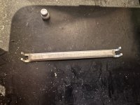
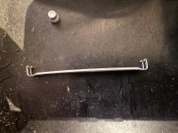
P.S. can anyone shed light on what this thing is from, found it rattling round the chassis along with the two case screws?

IMG_9536.jpgIMG_9535.jpg
 
Sometimes power transformers make a thud when you first turn them on, other times not. Counter intuitively, they draw less initial current if they are switched on right on the peak of the line voltage cycle, rather than when its near zero crossing. This is because at that moment when they are running normally the flux field is zero and the magnetization current zero at that time. When they are initially switched on near zero crossing the magnetic field has not been established yet an it takes a few cycles to get it operating. So for example, electronic zero crossing switches are not good on transformers, fine/good for resistive loads though.
 
The chirp is good. It indicates the initialisation process is running!

Voltages all look good.

Try the monitor now...

The clip is not something standard for a PET. It is likely that there was some add-on cards present at some time in the past, and this is a hang-over from their removal.

Dave
 
It looks like a strain relief clip of some sort for a ribbon cable.

Add-on cards for a PET were things like memory boards and the SuperPET.

It would be a shame if this machine had some extra boards and the previous owner parted them out.

Dave
 
It looks like a strain relief clip of some sort for a ribbon cable.

Add-on cards for a PET were things like memory boards and the SuperPET.

It would be a shame if this machine had some extra boards and the previous owner parted them out.

Dave
It looks vaguely familiar, can’t put my finger on it.
Thought I’d ask as this is my first time inside a PET.

Will plug the monitor in when I get home tonight.

Robert
 
Looking for logic probes. The prices have gone up a bit since Maplin went bust!

I have found what I was looking for at CPC FARNELL:

1727794343519.png

This unit has a switch for TTL/CMOS.

It has a red and green LED to indicate the state of the signal.

It has a yellow LED to catch pulses.

It clips onto an external +5V supply (for TTL).

There are similar ones for sale, at cheaper prices - but you are looking at Amazon, AliExpress etc. I leave that to you as to whether you want to go down that route or not.

I can't see RS or Digikey selling one though (according to their respective websites).

Dave
 
Looking for logic probes. The prices have gone up a bit since Maplin went bust!

I have found what I was looking for at CPC FARNELL:

View attachment 1287289

This unit has a switch for TTL/CMOS.

It has a red and green LED to indicate the state of the signal.

It has a yellow LED to catch pulses.

It clips onto an external +5V supply (for TTL).

There are similar ones for sale, at cheaper prices - but you are looking at Amazon, AliExpress etc. I leave that to you as to whether you want to go down that route or not.

I can't see RS or Digikey selling one though (according to their respective websites).

Dave
Thanks Dave I’ll have a look
 
Back
Top