Hello everyone. I recently purchased a 1084P (mono). There is sound on the monitor but no image. I connected a camera for testing. The sound comes out perfect. But still no image. There is no static on the monitor screen. There is no buzz either. From what I understand there is low voltage but no high voltage. I opened the CRT cover. I emptied the tube. There is no visible problem with the motherboard. The capacitor next to the optocoupler was giving an error in the measurements on the PSU. I removed it. I measured it and saw that the capacitor was OK. When I change it it gives an error. The optocoupler legs did not show any values. Could it be broken? When I measured HOT, it gave a normal value. Where should I look for high current? Thank you in advance for your help.
- VCF South West - June 14 - 16, Davidson-Gundy Alumni Center at University of Texas at Dallas
- VCF West - Aug 2 - 3, Computer History Museum, Mountain View, CA
- VCF Midwest - Sept 7 - 8 2024, Schaumburg, IL
- VCF SoCal - Mid February 2025, Location TBD, Southern CA
- VCF East - April 2025, Infoage Museum, Wall NJ
-
Please review our updated Terms and Rules here
You are using an out of date browser. It may not display this or other websites correctly.
You should upgrade or use an alternative browser.
You should upgrade or use an alternative browser.
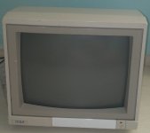
Commodore 1084p (mono) problem.(There is sound. There is no image.)
- Thread starter KENSA83
- Start date
Hugo Holden
Veteran Member
Hello everyone. I recently purchased a 1084P (mono). There is sound on the monitor but no image. I connected a camera for testing. The sound comes out perfect. But still no image. There is no static on the monitor screen. There is no buzz either. From what I understand there is low voltage but no high voltage. I opened the CRT cover. I emptied the tube. There is no visible problem with the motherboard. The capacitor next to the optocoupler was giving an error in the measurements on the PSU. I removed it. I measured it and saw that the capacitor was OK. When I change it it gives an error. The optocoupler legs did not show any values. Could it be broken? When I measured HOT, it gave a normal value. Where should I look for high current? Thank you in advance for your help.
There is not nearly enough information to answer your question, there are no details about how you measured components, or what rationale you had for checking any , in any specific parts of the circuit, or the reasoning behind why you think "high current" could be a factor anywhere in the circuitry.
Or why you suspected, or concluded, there was some sort of "optocoupler error". Or what capacitors you measured and how you checked them (with what tools/meters).
None of the post makes a lot of sense, at least to the extent that could help someone else help you fix this VDU. Or what the term "emptied the tube" means, if you discharged its final anode, that was a completely unnecessary step, presumably you got that from You-tube where misinformation abounds.
If you want help on this you need to :
1) post the schematic of the vdu, so that everybody agrees what components and circuit points they are talking about.
2) explain what test equipment (meters types, scope etc that you have).
3) the results of any tests you have done on various points in the circuit. How did you measure the HOT for example ?
Saying the "capacitor next to the optocoupler" is of little help and parts need to be identified with specific reference to the schematic.
Remarks like "the optocoupler legs did not show any values" makes little sense to the reader of the post.
4) A remark on any experience you have fixing VDU's, if any.
Otherwise, anyone reading your post would need a Crystal Ball to try to help you with the problem.
daver2
10k Member
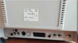
Does this service manual correspond to your monitor?
Let's make sure we have the correct manual for the monitor...
Electrical safety first!
What experience have you of working on electronics systems (in particular monitors)?
What test equipment do you have?
There is a warning in the manual I have located regarding using an isolating transformer. Part of the electronics is connected directly to the incoming mains supply.
I would also use a residual current trip device also.
Dave
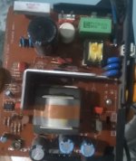
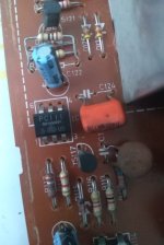
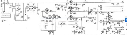
Hello Hugo. Firstly, thank you for your reply. I agree with you that I didn't provide enough information. I have basic electronics knowledge. I've never repaired a monitor before. I can use a multimeter. I currently only have a multimeter as a measuring device. If we start the problem from scratch. My monitor is a Commodore 1084(not s). When I turn on the monitor, the red power light is on. A faint sound comes from the speaker. When I connect a camera to the composite output the audio works fine. However, no image appears on the monitor (black screen). I don't feel any static on the screen glass. I increased the brightness settings on the front of the monitor and the result is still the same. First of all, the first thing that came to my mind was that the psu might be problematic. I measured capacitors, resistors and diodes in the psu. I found that C122 was shorted. I took it offline and measured it and realized it was solid. I replaced it with another capacitor of the same capacity. The result is still the same. I am sharing the psu circuit diagram and psu picture of the monitor. I don't quite know where to start.There is not nearly enough information to answer your question, there are no details about how you measured components, or what rationale you had for checking any , in any specific parts of the circuit, or the reasoning behind why you think "high current" could be a factor anywhere in the circuitry.
Or why you suspected, or concluded, there was some sort of "optocoupler error". Or what capacitors you measured and how you checked them (with what tools/meters).
None of the post makes a lot of sense, at least to the extent that could help someone else help you fix this VDU. Or what the term "emptied the tube" means, if you discharged its final anode, that was a completely unnecessary step, presumably you got that from You-tube where misinformation abounds.
If you want help on this you need to :
1) post the schematic of the vdu, so that everybody agrees what components and circuit points they are talking about.
2) explain what test equipment (meters types, scope etc that you have).
3) the results of any tests you have done on various points in the circuit. How did you measure the HOT for example ?
Saying the "capacitor next to the optocoupler" is of little help and parts need to be identified with specific reference to the schematic.
Remarks like "the optocoupler legs did not show any values" makes little sense to the reader of the post.
4) A remark on any experience you have fixing VDU's, if any.
Otherwise, anyone reading your post would need a Crystal Ball to try to help you with the problem.
Attachments
Hugo Holden
Veteran Member
OK.
Did it come to your mind that the PSU could have a problem, because you measured the outputs of the PSU with your meter and they were not normal ?
That is the first thing to do, check the power supply voltages with your meter and report them here.
If you look at the schematic you will see that there are a number of resistors, after the PSU outputs, which have a Triangle symbol beside them on the PSU outputs and inside that symbol have an exclamation point. This is to alert you to the fact these are "safety components". In general, for resistors, this means they are of the fusible variety, and they can, like a fuse, go open circuit. You can test these in circuit on the OHMS range on your meter (obviously with the power off) and see if any are open circuit. (If you read a lower value on the meter than the resistor's marked value that is ok, for an in circuit test, but the resistance should not measure substantially higher than its marked value.
These psu's can malfunction due to a fault in the psu circuitry, or they can malfunction if one of the PSU's outputs is overloaded, the reason is that the feedback that keeps the psu oscillating is derived from the transformer windings. This is how the SCR with the crowbar circuit works on the +125V rail, it simply shorts out the main output if the supply goes over-voltage and that shuts it down. When the supply is running normally, the feedback via the opto-coupler reduces the on duty cycle to the main transistor driving the transformer primary and this down-regulates the voltage to a stable level. However, if there is a fault elsewhere in the VDU (example being a shorted H output transistor "HOT" or a high current consuming fault elsewhere) this will also cause the supply not to run due to overload and insufficient feedback to sustain oscillations.
At the moment we don't know if the supply started and then shut down due to over-voltage at its output, or if the supply failed to start at all, or if it is actually running and one of the fusible resistors is open, or if the problem is that the supply is overloaded from a fault elsewhere, this is why some testing with your meter and reporting of findings is indicated.
Also, be aware that the connections of the "common" of the components on the primary side (line power side) of the supply are not the same as those on the secondary side, which are isolated from the line side (Isolated by the transformer's insulation). This is why they drew those lightening bolt symbols next to the common connections on the line (live side) of the supply.
For now at least , I would suggest not doing too many tests on the line power side of the supply when the power is applied. As @daver2 suggested, to test the live side, it is better to have an isolating transformer. With line powered switch-mode PSU's, probably it is better that a person doesn't attempt repairs themselves unless they fully understand the dangers of line power & high voltages in terms of electrocution risks.
Last edited: