I don't know where the motivation comes from to replace the vintage analog supplies in vintage computers with modern switchmode psu's. I never do it.
There is the argument of course that they are more energy efficient, more compact and result in less generated heat inside the case.
To put it bluntly, the new SMPS's are anachronistic and don't really belong inside a vintage computer. While you are putting them in you may as well throw in an Arduino and replace everything else as well.
The original analog supplies are great and have extremely low noise.
The heat generation issue of the analog supply can be significantly mitigated by keeping the incoming line voltage low in the 100V region. As long as the S-100 boards with 5V regulators on them receive just over 7.5V the regulation remains good. About 8V to 8.5V is an ideal value and allows for some line voltage fluctuations, you simply power your computer via a line Variac and adjust it so the 5V regulator inputs on the S-100 cards are about 8V. Your whole computer will cool down.
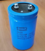
The massive uF value capacitors in these old computer supplies "add to the charm" of the vintage computer. These massive capacitors are still available if you take the time to look for them. I like to use new parts rather than trying to reform the old ones, but often that also works too.
There has also been a very foolish trend to try to replace the analog regulators like the 7805, TO-3 7805 (LM309k) or 12V versions on S-100 boards with switching equivalents to lower heat production.
I think this is sheer stupidity, because it grossly underestimates the design of the original analog regulators which have very advanced and effective self protection systems for current overload and thermal dissipation and they never fail in a manner which over-voltages all the precious IC's on your board. The worst you get from them, is over decades of use, their output voltage drops off a little. The same cannot be said for the switchmode equivalents where little thought, if any, has been put into failure modes, and these generate RF hash on the power supply rails.
People appear to want some sort of "quick fix" by eliminating the original analog supplies and throwing in a modern SMPS into a vintage computer. Or maybe it is because anyone can do it, even if they cannot understand the operation of the analog supply, or repair it properly. I don't think it is "vintage computing" (judgmental maybe, I'm known for it). And to me it seems somewhat lazy not to want to rehabilitate the original power supply back to its former glory. If there really is a significant thermal issue, the solution I go for is to add ventilation and/or cooling fans as I did for my SFD1001. disk drive, which does have an analog supply which runs notoriously hot.
") i am wondering if anyone has had luck modernizing the PSU in these machines similar to Alon's (Alegend on here) H7864-C which just uses standard ATX units?
i am wondering if anyone has had luck modernizing the PSU in these machines similar to Alon's (Alegend on here) H7864-C which just uses standard ATX units?