• Please review our updated Terms and Rules here

CRT repair help

The electric fences must be much weaker here, it's pretty common for kids to hold on to them for a laugh. It hurts but not much. I'm currently looking at my fuse board to upgrade things to RCBOs, though I'm still having one unprotected (other than amperage/breaker) circuit, I'm setting this up with a fast acting RCBO at my workbench, so I don't have to go downstairs to reset it. Relying on the house RCD (that protects all circuits) leaves you in the darkness swearing.
 
Part of it is not panicking. This excludes of course very high voltage & high current sources that coagulate your blood vessels, like the type of power sources linemen work with. No amount of calm behavior will save you in those cases.
I was once carrying a charged CRT, and my hand brushed across the anode connection and I sustained about a 50mJ shock (similar to what you would receive from a car or lawnmower spark plug). However, because I knew in advance it could not harm me and I had experienced many, I kept my composure and managed not to drop it on the floor. However, if I was a "shock novice", likely I would have dropped it.
 
Why is the convergence so bad? Did a magnet fall off the tube? Or the rings suddenly go loose and spin?
Convergence is affected by the focus and HV. It's normally not very noticeable, but when things are way off, it becomes obvious.

The lack of focus is the most concerning symptom I can see. Normally, the HV and focus voltages track each other so that even if the HV is too low, or too high, it should still be in focus. The only obvious thing that could cause the focus voltage to be out of track with the HV is the flyback. You can see in the schematic that the focus voltage comes from the same string of diodes as the HV. It's possible that something has happened to one of the diodes, causing the HV to drop, but not the focus voltage. A HV probe would be very helpful to see what's happening.
 
And I thought wisdom comes with age. Perhaps there are exceptions to rules, who would have thunk.
These are standard Specs for farmer's high power range electric fences and the energy stored in their capacitors, Still I wouldn't recommend actually doing it to prove the point that you would likely survive it, it is very unpleasant from these high power units, anything over 1J starts to get "nasty" and they certainly do pack a punch. One thing that ameliorates the risks, the Human or animal gets a single discharge from the unit and the discharges are widely spaced, so they tend to disconnect themselves from the fence and rarely receive more than one shock. Of course there are many other dangerous things on farms too, machinery etc.

A 20uF pulse capacitor charged to 320V DC stores about 1J of energy. These are the types of caps used in the units, often 2 or three of them. The voltage is stepped up and the current is lower, but that is all they can deliver energy wise as a single bolus. But, lets say you are working on a computer psu, it might have a 220uF capacitor charged to this voltage on the primary side, and that is about 11J. If the bleeder resistors have gone open (often do), you can sustain a very nasty, potentially lethal shock in a time frame after the VDU is turned off, before they self discharge. I always caution people more about the line power and B+ DC potentials in a VDU, because these are dangerous, far more so than the CRT's EHT supply. Despite this, youtubers make a big deal about discharging CRT's because of the pretty and they think scary sparks, but the energy there is usually well below 200mJ, except for a very large screen color TV set.

There was an exception though, prior to the invention of the Flyback style EHT supply (By Otto Schade at RCA labs in the 1940's) EHT supplies for CRTs were provided by line power transformers. I have three vintage TV's like this, all made in 1939. These were lethal, because they could source well over 30mA. Despite this they were supplied as kitsets for a home build, these sets were the "Widowmakers", but if you go to the end of the article, and read their remarks on high voltage hazards, the manufacturers were not too concerned about it, if you read what they said; " if you were determined to do it you could stand in the bathtub and play with the electric light fixture"

www.worldphaco.com/uploads/THE_MEISSNER_5_INCH_KIT_AND_THE_ANDREA_KTE-5.pdf
 
Last edited:
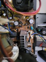
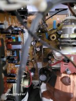
so i lifted up the legs of all the diodes in the areas ive shown in the photo and none of them seem bad. There all aroung where the flyback is on the board. Theres a lot more behind the neck of the crt which are quite hard to get to, they are next to the transformer, do you think its woth testing these? Im also not quite sure what the big ceramic capacitors are supposed to measure. the the biggest one measured 4.7nf.
thansk for any help
matthew
20240918_132558.jpg20240918_132545.jpg
 
I'd say get or borrow an HV probe (or as I did, five 200M resistors in series into a Tesco lunch box, fill with paraffin, and a 100uA meter), or a flyback/ring tester. Andy was referring to the diodes that are inside the epoxy of the flyback, and if one in that chain fails, high voltage goes down. You need to measure, not guesstimate.
 
I'd say get or borrow an HV probe (or as I did, five 200M resistors in series into a Tesco lunch box, fill with paraffin, and a 100uA meter), or a flyback/ring tester. Andy was referring to the diodes that are inside the epoxy of the flyback, and if one in that chain fails, high voltage goes down. You need to measure, not guesstimate.
A flyback ring tester is not required. A flayback can be tested in circuit with a dual resonance test with a signal generator & scope. The principles of this test are explained in an article I wrote about the physics of flyback transformers, pages 33 to 39:

www.worldphaco.com/uploads/RESTORING%20THE%20%20PET%20COMPUTER%209.pdf

However, if there is a fault in the divider chain from the EHT to the focus preset and the screen potentiometer, this won't stop the flyback transformer testing normally on either a ringing test or a dual resonance test.

It requires, as you pointed out, a high voltage probe to check the screen & focus voltages. And that requires a probe with a very high input resistance.

Most common TV EHT probes have an input resistance of about 100 Meg Ohms, but that is too low, if the divider chain on the EHT has a 500 Meg ohm total resistance which is typical. You need a probe with at least a 1G Ohm input resistance. A common probe like this is the 1000:1 ratio Fluke 80k-40 it has close to a 1000 Meg Ohm input resistance and plugs into a typical DVM with a 10 Meg Ohm input resistance. This is the one I use ( I think RS components part 442-8294) The only way to out-do this is to go to an electrostatic voltmeter, these are uncommon in modern electronics popular culture.

The fluke probe is available here, and also in the USA but they are not exactly a cheap piece of kit:


The CRT's screen voltage can be a lot less than 2.5kV so you could get away with a 100:1 2.5kV rated scope probe for that, but the focus voltage on a color CRT can be in the order of 3 to 5kv and a HV rated high input resistance probe is required. Still, if the screen voltage measured ok, likely the focus voltage would be ok because it would imply that the current in the bleeder chain across the EHT was normal. Sometimes there is an earth wire in this chain, if so, a sensitive current meter can be inserted in this leg, to see if the current is as expected, typically at about 20kV/400 Mohm or about 50uA.
 
Last edited:
and if not just 1, but all the diodes fail internally, you'll have an AC flyback. Like in olde timey vacuum tube television sets. For a short time at least, until the high frequency corona eats through the epoxy and shorts windings through:

 
and if not just 1, but all the diodes fail internally, you'll have an AC flyback. Like in olde timey vacuum tube television sets. For a short time at least, until the high frequency corona eats through the epoxy and shorts windings through:

In some cases, when the EHT rectifier inside the encapsulation of the EHT coil's insulation on a monochrome VDU shorts out, the VDU can be repaired by adding a new EHT rectifier in series with the EHT cable. I keep some EHT rectifiers for this purpose. It is not useful or quick fix on the typical color VDU, because the focus bleeder chain has AC applied to it with the internal shorted rectifier. But, it can be done if another focus and screen control & bleeder chain is added after the the new EHT rectifier.
 
Back
Top