• Please review our updated Terms and Rules here

Custom de-soldering tools.

Hugo Holden

Veteran Member
Joined
Dec 23, 2015
Messages
5,385
Location
Australia
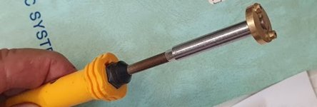
Over the years I have machined many de-solder tools (bits) for soldering irons, to help remove various IC's and other oddball parts.

One handy iron are the Antex types, because the bits slide on without a retaining collar, meaning that you can sacrifice a new bit (they are iron clad copper), and stake it into to any type or shaped head that you want.

Recently I was looking for some rare pcb mounted tactile switches in a Yang SBC, a few of them have lost their Mojo in that they are not tactile and clicky anymore. The type made by C & K are rated for hundreds of thousands of operations and they would have had nowhere near that, but I think the synthetic materials in some of them have degraded after more than 40 years.

The thing is though, these switches have two long stiff mounting pins that are about 0.8 to 0.9 mm diameter. I'm fairly certain that they pass through 1mm plated through holes and even with my best rework equipment I highly doubt if I could separate the pin surface from the inner wall of the plated through hole, and most likely I would destroy the pad and or plated through hole. And since the pcb is the most valuable part, in this case I decided to make a de-soldering tool. It took over an hour to make it with the aid of my mini-lathe and hand filing. (photo attached). the holes are spaced at the exact spacing of the pins, which can slide up into this tool. This way both the pins & solder can be heated to the same temperature, the solder thoroughly melted first and the switch withdrawn from the pcb, and the sucker used to clear the holes afterwards. Of course I might not need this if I used two soldering irons and had three hands.

Now I'm just waiting for the new switches to arrive.
 

Attachments

  • Tool.jpg
    Tool.jpg
    60.5 KB · Views: 39
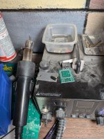
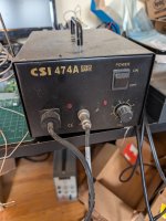
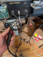
I would use a hot air station with a small diameter orifice and hit it from the back side until the solder flowed, then slowly wiggle it out.

1727401188668.jpeg
 
Wish I had a picture but I had a welder soldering iron tip I dremeled out and put it on My circuit specialist blackjack dissodering gun. Wish I still had that thing but I pretty much wore it out. They stop caring parts for it so I had to migrate over to Hakko and get one of those blue and yellow ones.
 
I would use a hot air station with a small diameter orifice and hit it from the back side until the solder flowed, then slowly wiggle it out.

View attachment 1287017
I have used these too, but found they are more harsh on the pcb and heat the pcb around the pins a lot more, in some cases excessively and you would have to alternate from pin to pin because the two pins are relatively widely spaced. Often people try with a single bit soldering iron too, alternating between two or more spaced pins and wiggling the part as one of the pins is cooling down while the other heated, but it is more stressful on the pcb. This is why I prefer custom bits. Also with both the pins heated at the same it does not need to be wiggled and can pull directly out/off.

The main problem is that if any force is being applied to the part, that the moment where the solder on any pin is not fully melted, but still hot, this is the condition that causes the tracks to lift from the pcb. This is why the custom tools work better most of the time, because you can ensure that all the solder on all the pins is simultaneously melted, before any force is applied to the part and it completely avoids track & pad damage.
 
I'm with you. I have found that modern circuit boards are remarkably resilient to heat but I can't speak to the older ones.

I also use an IR rework station, which has a base heater plate then applies IR with a bulb from above - you heat the whole section of the board up, then hit it with pulsed IR until the solder liquifies then pull things up. But I don't think the switches would like that very much.
 
I have used these too, but found they are more harsh on the pcb and heat the pcb around the pins a lot more, in some cases excessively and you would have to alternate from pin to pin because the two pins are relatively widely spaced. Often people try with a single bit soldering iron too, alternating between two or more spaced pins and wiggling the part as one of the pins is cooling down while the other heated, but it is more stressful on the pcb. This is why I prefer custom bits. Also with both the pins heated at the same it does not need to be wiggled and can pull directly out/off.

The main problem is that if any force is being applied to the part, that the moment where the solder on any pin is not fully melted, but still hot, this is the condition that causes the tracks to lift from the pcb. This is why the custom tools work better most of the time, because you can ensure that all the solder on all the pins is simultaneously melted, before any force is applied to the part and it completely avoids track & pad damage.
FWIW in my shop before I retired from the feds back in 2007, we had a dedicated repair bench which included a Pace desoldering station. The unit had a floor pedal for suction with a variable heat control and the pen had multiple detachable points for precision placement on those PCB joints. Also, there was a filter built into the handle. That unit was in service for nearly 20 years. I would image a tool like this would probably run well over $1K US these days. (Well worth it of you're into this type of repair work on regular basis).
 
Oh, is it just TH? Maybe I misunderstood the problem. There are TH solder suckers available as @Agent Orange said. They work quite well. Mine's a cheapie

1727459307607.jpeg
1727459344282.jpeg
 
Yes the problem is misunderstood.

The trouble with suckers though, no matter how powerful, if you have a situation where a round pin diameter is only a tad smaller than the internal diameter of a plated through hole, the pin will often be opposed to the internal wall of the plated through hole. And, because the radii of curvature of the pin surface and the hole perimeter are so similar the contact area is broad, there is little solder to clear over a circumference of more than 30 to 60 degrees with the sucker. So the pin remains attached to the plated through hole after sucking and won't break free. This is why its better to have a custom tool to melt the solder on all pins simultaneously, without overheating the general pcb area at the same time.
 
Last edited:
They used to sell this solder-like metal that you simply soldered all your pins on a chip with a hot iron ( over 400 degrees ) and it would keep the solder runny for about 20 seconds. Whatever it did really lowered the melting temp of solder... I remember they used to sell it at Worldwide Electronic Components here in WA. That was supposed to be good for chips up to 40 pins if you were fast enough, but I think the main intent was flat surface mount chips, the idea being you just went around them with a hot iron then lifted the chip away.

Also, while not recommended, I know a guy who had a jar full of mercury and realized he could just add a dot to any solder connection and wait, and a bit later, it would just drop out, or come out with minimal pulling. He did hundreds of boards with that jar in he 80s, and just pulled and cleaned all the chips and sold them off in jars, kind of like they do in China now. I wonder how much lead a single jar of mercury can dissolve?

I've shaped some tips for my irons, but never anything complicated. I suppose with a CNC now, I should be able to make small copper tips for the purpose - I never really considered that before. Though I'm not sure how to fit them to a modern iron... I'd have to think about that.
Brand name is Chip Quick. I've used it a couple of times and had good results. It really does extend the liquid time of the solder joint.
A word of warning... Flush the area with regular solder before re soldering component.
You want to remove as much of the lo temp solder as you can. It will make the joint brittle.

Found it - thanks - Been curious about that for a while.

 
Yes the problem is misunderstood.

The trouble with suckers though, no matter how powerful, if you have a situation where a round pin diameter is only a tad smaller than the internal diameter of a plated through hole, the pin will often be opposed to the internal wall of the plated through hole. And, because the radii of curvature of the pin surface and the hole perimeter are so similar the contact area is broad, there is little solder to clear over a circumference of more than 30 to 60 degrees with the sucker. So the pin remains attached to the plated through hole after sucking and won't break free. This is why its better to have a custom tool to melt the solder on all pins simultaneously, without overheating the general pcb area at the same time.
Yes, this makes sense. The technique is to use the solder sucker to melt the solder, then start the vacuum. Then move the tip around in circles such that the pin is in motion the entire time the solder is getting sucked out *and* isn't able to re-attach to the solder because it's cooling and moving constantly.

This works great with a little practice, but in your case the diameter of the pin is so close to the diameter of the hole that it would be iffy. I'd love to try it because there is no downside. If it worked then the pin moves freely, if it doesn't then you'll know instantly.
Exactly. In the case in point , which is why I manufactured the special tool, this cannot be done because the not only is the pin too thick and stiff for any significant sideways movement in the hole anyway, the clearance is too low for it to allow any significant movement for a sucker to work.

I have made many custom IC removal tools too, for surface mount IC's and these tend to give better results without track & pad damage than any other method, it just takes time to machine them.
 
Or get a chunk of bismuth and do a little shaving.
I didn't know what Chip Quik was made of. Did a bit of reading.
A mixture of bismuth and tin/lead solder can have a melting point as low as 98c.
Wow, it will melt in boiling water!
 
Exactly. In the case in point , which is why I manufactured the special tool, this cannot be done because the not only is the pin too thick and stiff for any significant sideways movement in the hole anyway, the clearance is too low for it to allow any significant movement for a sucker to work.

I have made many custom IC removal tools too, for surface mount IC's and these tend to give better results without track & pad damage than any other method, it just takes time to machine them.

Do you CNC machine, or hand machine the tool parts?
 
Do you CNC machine, or hand machine the tool parts?
I just hand make them mainly, but I started out with a disc of brass that I machined from a cut off, drilled the center in the lathe and two small holes in the drill press and hand filed the material around the holes, machined a spare soldering iron bit to fit and staked that in by hand into a countersunk area on the face with the projecting parts for a good thermal bond.

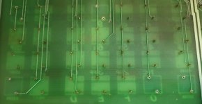
The clearance between the plated through holes and the pin was diabolically narrow, much worse than I had imagined it would be, I was expecting about a 0.1mm clearance at least because I figured the pcb designer would have known the switch pin diameter and selected at least 0.9mm holes.

The plated through hole internal diameter is 0.8mm and the surrounding pads only about 1.4mm diameter, but the pins are rated on the switch data sheet at 0.8mm +/- 0.01. Measuring the switches I removed for replacement, the pin diameter on them is 0.79mm to 0.8mm ! Probably when they were fitted, some of them would have been a press interference fit in the holes prior to soldering. A total impossibility for a solder sucker. I'm glad I made the tool or likely the pcb would not have survived the removal, unless like I say I had two soldering irons and 3 hands.

I'm not much of a believer in tiny holes and small pads and microscopic vias, not if there is truckloads of room on a large pcb, its better to leave more copper there.
 

Attachments

  • pcb.jpg
    pcb.jpg
    100.9 KB · Views: 8
Last edited:
Back
Top