• Please review our updated Terms and Rules here

Hello my old friend - TRS-80 Model 1

syzygy

Veteran Member
Joined
Apr 22, 2023
Messages
670
Location
North East USA
One of the reasons I joined here was to resurrect two TRS-80 Model 1 computers. I would do some work....on the monitors...on the floppy drives...read some old disks using a grease weasel...tested some power supplies...but only once tried to boot.

I "wander" on projects. Sometimes that bother me and I started a thread to learn how other people manage their projects. Several times I read [paraphrasing], when I get tired of a project, I box it and, maybe get back to it some day....I LIKE THAT IDEA.

So, I boxed my 8052-AH-BASIC, 8040 board, and a few others and decided that I had the time and interest to get back to the Model 1. I have two CPU/Keyboard units [one with a smashed case], several floppies and one expansion interface.

This one was my original TRS-80 that I bought refurbished from a local RS in ~1981 or so. I used the @#!& out of it and enjoyed and hated it many times over. After a thorough cleaning and inspection, I powered up to be greeted by:
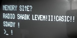
memsize 1 20240824_191013.jpg

Hey, I was HAPPY to see that! I have read enough of the reference manual to understand, pretty quickly, that it looked like one bad video memory chip [b0, Z48). After replacing that [made much more difficult by a thoroughly stupid mistake], I saw:
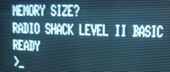
memsize2 20240825_193250.jpg

Sweet!

I then had to reflow the solder on every single keyboard switch...forgetting the '4' key until noticing that one was missed...no matter...keyboard cleaned and almost no bounce at all. I wrote a couple of stupid BASIC programs and giggled at seeing this thing work after, I don't know - 40 years of schlepping around in a box.

Then I noticed the power LED no longer lit. N/P just had to re solder it and eventually replaced it with a brighter one that had longer leads.

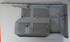
Now, on to the case. Remember, I said I had two such units...one bottom case (the one that originally went with this unit, got smashed up, so I used the remaining better bottom piece. Except the screw holders are so %^@$# old and cheap that the plastic just cracked away when I opened it. I knew this and a while ago, I had someone print out some 3D replacements. There are several around because this is a chronic problem. This was not easy for me as I am lacking those skills. I sawed off the remains of the posts and struggled quite a bit with the nervous placement. I used epoxy rather that super glue to give me a few minutes to adjust, if needed.

Here they are taped to check the positioning before gluing.
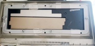
3d screw holders 20240827_162316.jpg
One other point on these, the holes had to be drilled because even with the few original self threading screws that I had, I could not get through the plastic. A 1/8 " drill did the job, but I think I messed up the angle a bit on one of them. Additionally, the original screws had to be rust-removed and wire-brushed. Bottom line is that 4/6 worked well and that was "good enough". The other two may be problematic because I don't have the right screws [I see them in the reference handbook, but Home Depot did not read that - anyone who knows where I can get the actual replacements, please let me know].

So, now I am cooking!
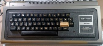
M1 2024 20240829_133435.jpg

Time to see if I can actually load a cassette. First off, I found two CTRs:
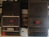
CTRs 20240829_131847.jpg

I could get no sound out of the CTR-80A (which was probably why I ended up buying a CTR-73 way back when ...and...after lots of cleaning...it worked!
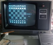
microchess 20240829_111154.jpg

It has been a productive two days.

While I am rolling, I may break out the other CPU unit and see where that one is at. Then, the EI with the floppies....at least that is the plan.
 
Last edited:
So, it's on to friend #2.

Did the cleaning and inspection; including removing socketed chips and spraying them and cleaning them..contact cleaner / ethanol / fiberglass pen. Z10 and Z11 were both in sockets on this board and were quite tarnished.

Still using the known good power brick and monitor (from friend #1)...I power up....
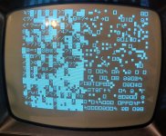
friend 2 s1 20240829_180231.jpg

A quick power cycle takes me to a 64 character garbage screen and it looks like the same (every other one) as the 32 character screen..
f2 s2 20240829_180244.jpg

*drat* and *sigh* and *oh crap*

Now I have seen such screen shots in a dozen places at least...on Utube and threads on this forum and elsewhere.

So, I start....and as I do, I am thinking "replace what you can first - don't go to the solder iron and removing chips unless you have replaced anything that you can replace easily and that makes some sense.

I check the voltages and the shunts. Everything is fine there.

I replace all the 16K 4116s - they are in sockets and I have pulls from gosh knows when...same screen. I started looking for 2102s for video ram and I start fine reading the reference manual and the Sam's photo facts. I am groaning.

It occurs to me that I have a known good Z-80....from the first machine. I use that on this board and holy moley, "Memory Size?" comes up!!

I order two Z-80s on Amazon for $12.68...they came today (unbelievably quick). I know they are likely cheap knock-offs but I can get them cheap and quickly...they even came with two cheap sockets....and they work (at least the one I put in).

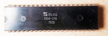
So, good bye old Z-80 from 1978 and...
z80 old 20240831_171331.jpg


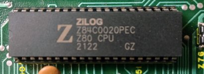
Hello new Z-80, happy to meet you.

z80 2 20240831_171345.jpg

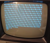
I write a "hello" program on a bouncy keyboard and run it for an hour or so - N/P
hello screen 20240831_170940.jpg

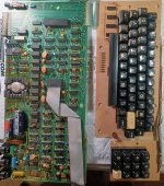
I am pleased. This one is a nicer machine than my original one. Has the numeric pad and an RS-installed LC mod.
TRS80 n2 20240831_183255.jpg

So, I will need to do the routine of cleaning and re-flowing solder joints on the keyboard....then I need to think about the case...that is the one that got smashed in-the-box.

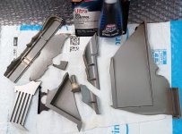
smashed case 20240831_183507.jpg
I probably have most of the smashed pieces, but I am sure there are slivers. Question, do you think I could super glue that to a functional state?

I did come across this fellow who did the work for 3D printed tops and bottoms. I guess you need a large 3D printer for that and he recommends you go to a site and ask for a bid. does anyone have any experience with such a case or can anyone recommend an alternative?
 
Last edited:
I probably have most of the smashed pieces, but I am sure there are slivers. Question, do you think I could super glue that to a functional state?

I've tried that and the results were not very good. It did work, but the end result looked more like Frankenstein than I wanted.
And while that fixed the broken pieces, it didn't address the root problem: The plastic is simply brittle at this age.
 
Interesting post, thank you for sharing. I'm not a technically proficient but did manage to do the factory equiv, PAL mod to my model 1 I bought from the US. Still running 120v psu's on an inverter.
 
I've tried that and the results were not very good. It did work, but the end result looked more like Frankenstein than I wanted.
And while that fixed the broken pieces, it didn't address the root problem: The plastic is simply brittle at this age.

What did you end up doing? Did you replace it some how or?
 
What did you end up doing? Did you replace it some how or?
I didn't.

For my Model I Level I, I simply left it as a display piece, even though it works fine. The case is simple too brittle.
For the Expansion Interface, I haven't decided. I ended up getting a Quinterface/FreHD combo, so I really don't need it. But if I get the time, I'll probably have a new case 3D printed to put the hardware in. I really don't see any other option.

frank trs80 1 20240902_085101.jpg
Frank trs80 2 20240902_142138.jpg
I now understand your Frankenstein comment :) Hey, a bottle of glue is cheap. I will test it out tomorrow, and, if it holds, I will use it on friend #1 - the original.
 
So, I have finished the two keyboard/cpu units. They both work, more or less, so I am happy about that. The shattered and glued bottom went on my original unit and seems to be holding up so far, and the better bottom went on the second unit. I really do need to look into the 3d printed cases because, as has been noted, this plastic is well past its prime.. After I clean up and reclaim some work space I will decide on whether to tackle the EI at this time. I may wait a bit.

I dug out some old cassettes and they load ok although I did have to re-glue the little fabric pressure pad on a couple of them.

Most TRS-80 M1 owners remember this one...I had not seen/heard it in decades.

dd 20240902_202550.jpg
 
Curious what the lc mod looks like.

There were many out there.

On my original M1, I installed the simplest possible conversion from an article by Don Lancaster, which was little more than a piggy-backed RAM chip. I think it was my first experience with an IC.

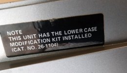
The 2nd M1 has the LC mod. installed by RS. It still has a sticker on the case.

LC tag 20240904_113336.jpg


The RS installed one gave you the better character generator as I recall, see here. Hopefully, I am not too far from seeing them in action.
 
On to the Expansion Interface.

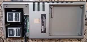
This unit is clean!
EI 1 20240903_202302.jpg

EI 2 20240903_192840.jpg

I hit the screws with some WD and waited. As I got them to turn without breaking the posts, I hit them again and waited. They all came out easily. I wire brushed them and cleaned up all of the WD.

Treated the connector ribbon with contact spray and ethanol. Wiped down all of the key connections in the same way. Those old silver connectors were a monstrosity. Great conductor silver, except for that pesky tarnish. Those gold add on connectors were a treasure - and expensive, as I remember. Had some special gold wipes for them.

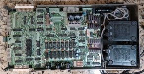
I can see that this is the revised board and no buffered cable needed - just as I remembered. I see the 32K RAM.

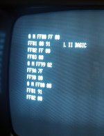
Connecting up the unit went flawlessly. Next, I needed to, somehow, get an idea if the RAM was seen. Activating neuronal pathways that have been dormant for decades, I loaded a T-Bug cassette. Digging up a manual, I just did a simple modification of an address in that 32K space...and it worked!

TBUG 20240904_125042.jpg

Next stop - the floppies!
 
Last edited:
The RS installed one gave you the better character generator as I recall, see here. Hopefully, I am not too far from seeing them in action.

The "better" character generator on the Radio Shack mod served two functions. The first, and less important win, was the original generator displays oddly displaced lowercase letters; all the letters with descenders (j,g,q, etc) and, for some reason, the lowercase "a", were rendered too high in the character grid. (Strictly speaking this displacement, other than possibly the case with the letter a, wasn't actually a "mistake"; the generator appears to have been designed for a system which would recognize these characters that need to be displaced and move the whole grid down a few lines. The TRS-80's video circuitry isn't smart enough to do that; it uses 12 scan lines for each "character cell" to accommodate the 2x3 graphic blocks, but items from the character generator can only display 8 lines over 4 blanks.) The replacement character generator fixes the lowercase letters so they look all right restricted to their 8 scanlines. (IE, they're similar to the characters in most computers that had 24/25 line displays, with descenders that would touch the top of the characters of the next line if it wasn't for the 4 lines of padding the TRS-80 adds.)

The other thing the RS character generator does is replace the 32 weird graphics symbols the original generator has in positions 0-31 with a duplicate of the uppercase characters (and others) at positions 64-95. This works around a weird bug/feature/oddity/just-plain-weirdness in the BASIC ROM. This bug is why many (most?) third-party/homebrew lowercase mods for the Model I have a switch to disable it; this bug caused garbage to be printed in place of uppercase characters by the main print routines in Level II BASIC unless a lowercase driver was loaded. (Some third-party mods incorporated circuitry to shift the uppercase letters down to 0-31, accomplishing the same thing, but the switch was easier.)
 
I have been making progress, but have hit an impasse. I have a 4-drive RS cable, where they pull pins to define the drives. A shunt on the drive itself has all drives addressed and the cable does the selecting. I also have a single cable with no select lines pulled.
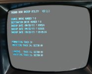
trs80 trsdos backup 20240905_144140.jpg
I have four drives total. One is dedicated to my greaseweasel and two SA400 TRS-80 and a Tandon TM100-1a. I had previously tested these drives to a small extent.
One SA400 works well as D0. After located and extensively cleaning a TRSDOS 2.3 diskette, I was able to boot and then backup that disk to two nos DD diskettes with no problem.

This is going to take some time :(


The second SA400 has decided to be funky and I don't know what the shunts should look like on the Tandon.
 
The worst part of which is that it took them 4 extra bytes of code to do it that way.

It is very weird. My personal hypothesis is that maybe there was a prototype version of the machine that used a Signetics 2513N or similar 64-glyph uppercase-only character generator that legitimately had the lowercase letters at positions 0-31, and Microsoft assumed that's what they had to program against? Tandy's bit-six-inversion shenanigans in the final hardware lets it display uppercase characters regardless of whether bit six was set for their ASCII codes when the hardware was written to, so they really should have backed that out, but... feh. In the end it really would have made a ton more sense to add that one extra SRAM chip. ;)
 
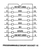
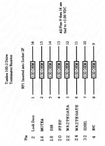
Shunts are as shown in the Attached Photo:

I use a 7 or 8 DIP Switch to select the one I want. You could also use a 4 position DIP as the
Drive Select is the ONLY position used.


Larry
 

Attachments

  • Shunt.png
    Shunt.png
    68.6 KB · Views: 5
  • Terminator.png
    Terminator.png
    174.6 KB · Views: 5
Thanks much @ldkraemer that was exactly what I needed. I thought that I had the service manual...and I did...and eventually found it :) I configured the shunt the same as the SA400 TRS-80 drive and let the cable do the drive select. It works!
 
Back
Top