• Please review our updated Terms and Rules here

IBM 5154 Enhanced Color Monitor Rejuvenation

Joined
Oct 4, 2022
Messages
48
Hello, I am trying to rejuvenate the tube on my IBM monitor and I can't find the required information.

The tube type is: M34JDU30X15

I need to know:
Heater Voltage: ??
G1 Voltage: ??
Neck Type: ??

Any help would be greatly appreciated.
 
I have been working with monochrome and color CRT's all of my life, including in a CRT re-gunning plant back in the late 70's.

Rejuvenation of CRT's doesn't really work, or in cases where it does the effects are minimal and temporary.

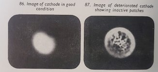
The main reason the CRT degrades with time is loss of emission from the cathode surface. This is because the coated emitting surface becomes contaminated with positive ions. An electron optical image of the cathode shows that dark spots of zero emission occur on the surface, when the % area of these is high enough, the emission drops too low. Some attempts at rejuvenation involve trying to blast these areas off, it seldom works and sometimes makes things worse. Or temperature cycling the cathode can help, a little. Many of the rejuvenator devices available in the 1960's were more snake oil than science. Though it didn't stop people wanting to find the fountain of youth for the worn out CRT, but they worked about as well as Dr. Scott's Elixir for baldness. Gas in the tube also poison's the cathode.

In addition the screen phosphor ages degrades in efficiency and darkens with time and puts out less light for any amount of beam current.

There is a way however to get more life out of a CRT, prior to it requiring re-building (A service that is no longer available on Earth). And that is to raise the cathode surface temperature by increasing the heater voltage. This causes the cathode to liberate more electrons. You can also adjust the screen voltage up a little on the CRT which helps.

Generally a CRT heater runs an orange color indicative of its temperature. You can increase the voltage so that it is yellow, perhaps to the level of a lantern bulb with a less than fresh battery, but not white. The heater , just like a lamp running off less than the its max applied voltage, can last in this condition for some years. There were devices made called CRT "Brighteners" that stepped up the heater voltage to do this for many models of TV set, but I don't think one was ever made for the 5154 and I have not seen one in a computer VDU, but you can always make one.

Most CRT's that arrived at re-gunning plants, had already been on a brightener for a year or two before they gave up and their guns had close to zero emission.

The g1 voltage you were wondering about, on its own, has no meaning. It is the relative g1 voltage to the cathode voltage that is important in determining the CRT's beam current. When that relative voltage is zero, the beam current is maximum, when the g1 is negative, can take as high as -50 to -80v for some CRT's the beam is fully cut off. But, if the g1 grid was grounded, that is equivalent to the cathode being 80V positive.

I would be cautious about connecting the CRT's gun up to any improvised device unless you fully understand the Physics of the CRT.
 
Hi Hugo,

I really appreciate your counsel on this. I questioned the validity of the rejuvenation process and watched a video that showed it done. It did work; However, I only saw 20 seconds of the results playing a video game. I assume the fix probably faded away over a few hours or days of use and the CRT went back to its original problem state.

Background: I replaced all of the capacitors a few months back. Everything has been working perfectly until a week or so ago. The screen has now gone to a fairly Red hue...I assumed this is because the Green and Blue have decayed and the Red is overpowering them (thus the rejuvenation idea). It's strange that every once in a while the CRT will work perfectly for a little while and then it will fall back to the red hue. This makes me think there may be another problem. I'd be interested in your thoughts on this somewhat intermittent issue.

Thanks,
Scott
 
What if I post the Sams instead?

I saw a recent video from Adrian's Digital Basement where it was suggested that the 5154 was a Samsung OEM monitor, and he showed a Samsung example that looked very much like a 5154 inside. Also the Tandy EGM-1 seems to be the same as what he showed, and the manual for that is on Archive dot org: https://archive.org/details/egm-1

I've got a Samsung monitor with the same FCC ID as the one that Adrian had, but a completely different plastic case. Then he found one in his stash that looked just like mine, but a different brand, so perhaps finding compatible CRTs for a 5154, if needed, might not be that hard.
 
Your symptoms sound like an electronic fault, not a bad CRT. CRTs generally fade out gradually over years, and don't come back intermittently. Occasionally shorts can develop inside the electron guns, but that usually causes the affected gun to turn on full blast.

To be sure, you need to measure the cathode voltages on each gun, ideally both when it's working, and when it's not.

If it's producing a good picture other than the red tint, then try adjusting it. Turning the red bias down a little might be all that's needed. The problem could even be caused by a dirty adjustment pot in the red video amp.

You only consider rejuvenation when all else has failed. That means it can't produce a good picture, even after careful adjustment, and you've ruled out electronic faults. Normally, by the time a CRT is failing, the picture will be dull, and lacking sharp focus. Usually, one gun gets weaker before the other two, never stronger like you're seeing.

I've had mixed success with rejuvenation, but only when using a well designed CRT tester. Often the result will only last minutes, or hours, but I've had some successes that are still working well after years of occasional use.

The CRT in the 5154 is a fairly common type. Earlier this year I replaced one that had a broken neck with the CRT from a cheap 14" VGA monitor. By luck, it was virtually the same CRT, and even the deflection yoke was the same. There was a slight difference in mounting that required adding some spacers.

I've seen 5154 that were made in Korea, and Finland. They were essentially identical inside, but clearly came from a different factory. I would assume the ones from Finland were made by Nokia. The ones from Korea were probably built by Samsung, or Goldstar. All of them use Japanese CRTs.
 
Thanks Andy,
I'm new to the CRT world so can you tell me where the RGB Bias adjustments are located?
Particularly, the red video amp?
 
I have been working with monochrome and color CRT's all of my life, including in a CRT re-gunning plant back in the late 70's.

Rejuvenation of CRT's doesn't really work, or in cases where it does the effects are minimal and temporary.

The main reason the CRT degrades with time is loss of emission from the cathode surface. This is because the coated emitting surface becomes contaminated with positive ions. An electron optical image of the cathode shows that dark spots of zero emission occur on the surface, when the % area of these is high enough, the emission drops too low. Some attempts at rejuvenation involve trying to blast these areas off, it seldom works and sometimes makes things worse. Or temperature cycling the cathode can help, a little. Many of the rejuvenator devices available in the 1960's were more snake oil than science. Though it didn't stop people wanting to find the fountain of youth for the worn out CRT, but they worked about as well as Dr. Scott's Elixir for baldness. Gas in the tube also poison's the cathode.

In addition the screen phosphor ages degrades in efficiency and darkens with time and puts out less light for any amount of beam current.

There is a way however to get more life out of a CRT, prior to it requiring re-building (A service that is no longer available on Earth). And that is to raise the cathode surface temperature by increasing the heater voltage. This causes the cathode to liberate more electrons. You can also adjust the screen voltage up a little on the CRT which helps.

Generally a CRT heater runs an orange color indicative of its temperature. You can increase the voltage so that it is yellow, perhaps to the level of a lantern bulb with a less than fresh battery, but not white. The heater , just like a lamp running off less than the its max applied voltage, can last in this condition for some years. There were devices made called CRT "Brighteners" that stepped up the heater voltage to do this for many models of TV set, but I don't think one was ever made for the 5154 and I have not seen one in a computer VDU, but you can always make one.

Most CRT's that arrived at re-gunning plants, had already been on a brightener for a year or two before they gave up and their guns had close to zero emission.

The g1 voltage you were wondering about, on its own, has no meaning. It is the relative g1 voltage to the cathode voltage that is important in determining the CRT's beam current. When that relative voltage is zero, the beam current is maximum, when the g1 is negative, can take as high as -50 to -80v for some CRT's the beam is fully cut off. But, if the g1 grid was grounded, that is equivalent to the cathode being 80V positive.

I would be cautious about connecting the CRT's gun up to any improvised device unless you fully understand the Physics of the CRT.
Hi Hugo, can you tell me where the CRT heater Voltage adjustment is? Thanks
 
Hi Hugo, can you tell me where the CRT heater Voltage adjustment is? Thanks
The heater voltage for the CRT is not normally adjustable, it either comes from one of the DC supplies or a winding on the horizontal output transformer or the PSU. In the case of the 5154, it is powered from a 6.3V half wave rectified pulsed AC source derived from a winding of a transformer in the switch mode power supply. The rms value of this wave determines the effective heating equivalent to a DC voltage. To get a higher rms value the diode (looks like D16, hard to read on my copy in parallel with C24) could have a resistor placed in parallel and this would increase the rms voltage because the heater would receive current on the other half cycle too...........

But, at this point I would not even dream of increasing the CRT's heater voltage and current (if I did I should wake up and apologize to the CRT), unless, it could be proven that it was down on emission, it probably isn't, as Andy says the symptoms are indicative of an electrical fault, nothing to do with the CRT at all.

Most faults that affect the relative color balance in color VDU's and TV's are not related to the CRT, though in the early days there was a struggle with Red phosphors for efficiency, so it always seemed to be the red gun that started failing first, but that problem was long overcome by the time that the 5154 was born.

Be aware that there are a number of color TV and VDU CRT's that could be compatible with the one in the 5154, in terms of the basing, gun, EHT requirements etc and appear to "work" However, the original CRT in the 5154 was a special part that had a super fine phosphor pitch to support detailed graphics. Somewhat like the one in the 5153. So if you ever did need a new CRT (and probably you don't) it better to find the exact part.

Also both in the 5153 and 5154, the CRT had extra tinting in the faceplate glass to improve the contrast in high ambient lighting. This works because the incident light has to pass through two layers of it to get from the phosphor surface back to the observer's eye. But the light from the phosphor only passes through one layer. All of the substitute CRT's I have seen for the 5153 for example don't have this and I suspect this is also the case for most substitue 5154 CRTs. In fact the faceplate of the 5153 CRT has the highest tint of any color CRT I know of. I think IBM specified an array of CRT features & parameters to the makers and for these they didn't use off the shelf pre-existing CRT's and they were especially made for the task.
Understood...Andy mentioned the RGB bias adjustments and in particular the red video amp...None of these adjustments are readily viewable...Looks like they may be on the hard to get to side of the video board? Can you confirm the adjustment locations? Thanks
 
The heater voltage for the CRT is not normally adjustable, it either comes from one of the DC supplies or a winding on the horizontal output transformer or the PSU. In the case of the 5154, it is powered from a 6.3V half wave rectified pulsed AC source derived from a winding of a transformer in the switch mode power supply. The rms value of this wave determines the effective heating equivalent to a DC voltage. To get a higher rms value the diode (looks like D16, hard to read on my copy in parallel with C24) could have a resistor placed in parallel and this would increase the rms voltage because the heater would receive current on the other half cycle too...........
An earlier diagram that I drew from my 5154 is at [here]. I remember that someone on these forums had a faulty 5154, and incorrectly deduced 'no heater voltage' when there was in fact heater voltage. They had removed the power supply from the 5154, and then connected the negative probe of the multimeter to the the metal case of the power supply.
 
Understood...Andy mentioned the RGB bias adjustments and in particular the red video amp...None of these adjustments are readily viewable...Looks like they may be on the hard to get to side of the video board? Can you confirm the adjustment locations? Thanks
The right side of the diagram at [here] shows seven potentiometers, corresponding to the seven shown in the video cage photo at [here].
 
Fantastic modem7...That's where I thought they were based on the SAM'S schematic I have...I have a nice project for this evening...Everyone have a great day/night depending on your location.
 
UPDATE: It was the Red Cutoff Potentiometer...Just needed to be cleaned and worked a bit. The screen is back to it's sharp, clear, and stable condition again. Thanks to everyone for your thoughtful help, direction, and expertise.
 
UPDATE: It was the Red Cutoff Potentiometer...Just needed to be cleaned and worked a bit. The screen is back to it's sharp, clear, and stable condition again. Thanks to everyone for your thoughtful help, direction, and expertise.
Intermittent preset pots are a real problem, it depends on how they were designed.

The rectangular style fully enclosed ones made by Bourns are very good, and the metal shell encased cermet types are good too, but there are many types not sealed to dust and fumes. There is a cermet open frame type used in vintage Tek scopes such as the 464, 464,466 etc with a grey plastic thumb-wheel (bad idea too because they get bumped sometimes in servicing the scope), that unfortunately were not sealed and they result in numerous intermittent failures. They respond to cleaning but a few years later, play up again.
 
Back
Top