Upcoming Events:
- VCF South West - June 14 - 16, Davidson-Gundy Alumni Center at University of Texas at Dallas
- VCF West - Aug 2 - 3, Computer History Museum, Mountain View, CA
- VCF Midwest - Sept 7 - 8 2024, Schaumburg, IL
- VCF SoCal - Mid February 2025, Location TBD, Southern CA
- VCF East - April 2025, Infoage Museum, Wall NJ
-
Please review our updated Terms and Rules here
You are using an out of date browser. It may not display this or other websites correctly.
You should upgrade or use an alternative browser.
You should upgrade or use an alternative browser.
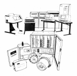
Identify minicomputer from sketch?
- Thread starter tech58761
- Start date
eswan
Experienced Member
dec vax-11
krebizfan
Veteran Member
Much of it seems to be an abstracted artist's impression of real computer equipment and tape drives look the same from everybody. The terminals resemble VT-52s with the offset display; the printers and support tables look DEC influenced. On the other hand, the VAX 11/780 had 2 rows of vents on the front of the top and bottom section of the CPU cabinet while the art has 3 rows of vents near the top of the front of the cabinet.
What is the source for the image?
What is the source for the image?
m_thompson
Veteran Member
In the front row: DEC LXY printer on the far left, next DEC LetterWriter 100 terminal, two DEC VT100 terminals
In the back row, two DEC RK07 27 MB disk drives, DEC 11/750 VAX computer, DEC TU10 Magnetic Tape Drive.
In the back row, two DEC RK07 27 MB disk drives, DEC 11/750 VAX computer, DEC TU10 Magnetic Tape Drive.
tech58761
Experienced Member
So a VAX system huh? Cool. This was from the cover of a handbook I came across some time ago.
It pertained to the equipment in the foreground - a system an electric utility could deploy to manage interruptible loads (air conditioners, water heaters, etc.) during system peaks, as well as the ability to remotely read meters, all using a 9-12kHz carrier overlaid on the 60Hz power lines. The large cabinet is the transceiver installed in the substation, and which tied into the distribution system using the coupler box next to it, and in the foreground is a load controller with two different kinds of remotely readable electric meters.
The minicomputer would have been in the main office and communicated with the transceivers to transmit load control commands and ping the meters for the readings. I would imagine as microcomputers became more popular in the late 1980s, the office side of the system would have evolved to reside on one or two PCs instead.
m_thompson
Veteran Member
So a VAX system huh? Cool. This was from the cover of a handbook I came across some time ago.
It pertained to the equipment in the foreground - a system an electric utility could deploy to manage interruptible loads (air conditioners, water heaters, etc.) during system peaks, as well as the ability to remotely read meters, all using a 9-12kHz carrier overlaid on the 60Hz power lines. The large cabinet is the transceiver installed in the substation, and which tied into the distribution system using the coupler box next to it, and in the foreground is a load controller with two different kinds of remotely readable electric meters.
The minicomputer would have been in the main office and communicated with the transceivers to transmit load control commands and ping the meters for the readings. I would imagine as microcomputers became more popular in the late 1980s, the office side of the system would have evolved to reside on one or two PCs instead.
I remember a project I worked on in the 1980s for Florida Power where a VAX communicated with power meters over the power lines. The interface in the VAX was fiber and the transceiver was on the high voltage side. They could read something like 100,000 power meters per day. Saved a lot of time and driving.

