• Please review our updated Terms and Rules here

ISA to USB - Are these anywhere to be found?

Even the listing I bought it from shows a 74LS245, and the schematic which I found online also shows that a 74LS245 goes in that socket. I found a 74LS245in my parts drawer and stuck it in the slot, then I stuck the board in the pc-104 slot and tried configuring the driver for the 4 I/O addresses that are available on the ISA version of this board. It didn't respond to any of them, 230 240 250 or 260. Next I read off the contents of the 16V8PLD, however I don't know how to interpret them. I will post it here if anyone can suggest what the PLD is doing and what port I might try setting the driver to.
 

Attachments

  • PC104ISA.PDF
    46 KB · Views: 7
  • 168v.JPG
    168v.JPG
    76.9 KB · Views: 3
I found a 74LS245in my parts drawer and stuck it in the slot, then I stuck the board in the pc-104 slot and tried configuring the driver for the 4 I/O addresses that are available on the ISA version of this board. It didn't respond to any of them, 230 240 250 or 260.
Well, this is the first we've heard in this thread about a driver, and also the first time we've seen this schematic of mysterious provenance. It's really a good idea, when you introduce something, to say where it came from and what you believe the connection is between that and the actual board you have.

Are you sure that the driver is the proper driver for your board? The schematic looks plausible, except for the extra ROM, which has very dodgy address decoding: it seems to plunk it four times into the middle of the 8086 address space. The code for the GAL on that schematic indicates that it's programmed to use the $130-$137 range of I/O ports.

Is the A0 pin on your board edge connected directly to the A0 pin on the CH375? If you read from port $130, what do you get? If you then write $01 to port $131 and then read again from port $130, how does that compare to the first value you read?

I agree that checking the GAL programming is a good idea. I wouldn't re-program it with the code on the schematic without verifying that the schematic actually matches the board.
 
Yes, I should have done a better job of explaining the assumptions I made. I had been using an ISA based USB "U-Disk" card like the one pictured at the top of this thread before I came across this PC-104 card. I assumed that they were basically the same since they looked so similar. I wanted to free up an ISA slot in the system I'm using, so I figured I could just take out the ISA "U-Disk" board and replace with this PC-104 "U-Disk" board and use the same driver.

Just before my previous post, I found another thread here on VCFed that had schematics for the ISA based board, and a readme file that seemed to indicate that my assumption was correct, the PC-104 and ISA based boards have the same schmatic: https://forum.vcfed.org/index.php?t...-use-isa-to-usb-card-in-ibm-5160.49356/page-2

A continuity test reveals that A0 on the CH375 is connected directly to A0 on the PC-104 board

If I read port 130, I get 0ff, next I write 01 to port 131, and go back and read port 130, it still shows 0ff.
 
Ah, your further explanation clears up a lot, thanks.

Just before my previous post, I found another thread here on VCFed that had schematics for the ISA based board, and a readme file that seemed to indicate that my assumption was correct, the PC-104 and ISA based boards have the same schmatic: https://forum.vcfed.org/index.php?t...-use-isa-to-usb-card-in-ibm-5160.49356/page-2

A continuity test reveals that A0 on the CH375 is connected directly to A0 on the PC-104 board
Well, that's a good sign that the schematic isn't completely different, at least, and lets us know that the lowest address bit is selecting A0=read/write data and A1=write command ports.

Another quick check you could do is confirm that pin 16V8 pin 15 (driving a signal named USB#) and CH357 pin 27 (CS#, negative logic chip select) are connected together, since the schematic indicates that.

If I read port 130, I get 0ff, next I write 01 to port 131, and go back and read port 130, it still shows 0ff.
Ok, so that means that either commands are not being sent to the CH375 command port or that reads aren't reading from the CH375 data port (or both). You should expect to read version number between $A4-$BF after writing a GET_IC_VER ($01) command.

I think the next step is probably to check the GAL; if they've gone so far as to put the wrong latch on the board, I wouldn't be surprised if the GAL isn't programmed properly, as Eudimorphodon points out. Unfortunately, I'm not very familiar with those, but perhaps someone else on the list will be able to look at the dump you made and see if it makes some sort of sense or if it's more likely the wrong code.

Another alternative, if examining the code dump directly isn't working out, is to put a scope on pin 27 (CS#) of the CH375, which should normally be held high, and see if it goes low at some point when you read various ports, to see if the 16V8 is actually generating the chip select signal for two or more ports.
 
The code for the GAL on that schematic indicates that it's programmed to use the $130-$137 range of I/O ports.

The “code” for the GAL is in a somewhat unusual syntax, but… I read “A9-A4:100110” as “100110xxxx”… which would translate to 260h as the base address? (Of course meaning the two I/O ports it actually uses are repeated 8 times up to 26Fh.)
 
The “code” for the GAL is in a somewhat unusual syntax, but… I read “A9-A4:100110” as “100110xxxx”… which would translate to 260h as the base address? (Of course meaning the two I/O ports it actually uses are repeated 8 times up to 26Fh.)
Ooops, yes; you're absolutely correct. I left a (binary) zero off the end of my previous calculation somehow.

@new_castle_j You should re-run that first read/write/read test against ports $260/$261/$260. (Though I suspect that, given your driver didn't work, this won't work. But either way, it will get us closer to figuring out where the problem is.)
 
Yes, Pin 27 of the CH375 has a direct connection to Pin15 of the 16V8 on my PC-104 board, and port 260 makes sense as that was the default for the ISA board. Dong the read/write/read test against $260/$261/$260 still showed a value of 0ff on 260 after writing 01 to 261.

I've never used the PC-104 expansion slot on this Advantec PCA-6743 ISA card before, and I should probably check whether there's a configuration in the BIOS or a jumper or something that is required to be set before using it. I assume that it's just an extension of the same ISA bus and that the two can operate concurrently.
 
Unfortunately, I'm not very familiar with those, but perhaps someone else on the list will be able to look at the dump you made and see if it makes some sort of sense or if it's more likely the wrong code.

@new_castle_j : can you attach the actual .JED dump (not a .JPG) to a post? There are tools floating around that can turn that back into human readable equations. (There very well could be someone on this forum hardcore enough to interpret a .JED just by looking at it, but that’s definitely not me despite having done some… moderately clever things with GALs.)
 
So... I tried using the jedutil in mame-tools on the .PLD from the dump, and it absolutely refused to do anything with it, saying "Fatal error: Invalid .JED file". Then I tried JED2EQN.EXE from the ancient DOS OPELJR tool set, and I got this:

Code:
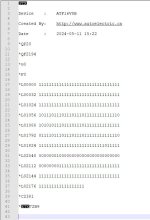
; JED2EQN -- JEDEC file to Boolean Equations disassembler (Version V063)
; Copyright (c) National Semiconductor Corporation 1990-1993
; Disassembled from usb.jed. Date: 5-14-124
;$GALMODE MEDIUM

chip usb GAL16V8

i1=1 i2=2 i3=3 i4=4 i5=5 i6=6 GND=10 /i11=11 o12=12 f13=13 o14=14
o15=15 o16=16 o17=17 o18=18 o19=19 VCC=20

@ues 0000000000000000
@ptd unused

equations

/o19 = vcc
o19.oe = vcc
/o18 = gnd
o18.oe = gnd
/o17 = gnd
o17.oe = gnd
/o16 = gnd
o16.oe = gnd
/o15 = /i2 * /i3 * /i4 * /i5 * /i6 * i11
    + /i2 * /i1 * /i3 * /i4 * /i5 * /i6
o15.oe = vcc
/o14 = gnd
o14.oe = gnd
/f13 = gnd
f13.oe = gnd
o12 = f13
o12.oe = i2 * /i3 * /i4 * /i5 * /i6 * i11

... And this is where it all goes pear shaped, because when you start comparing this with the PDF it becomes pretty clear that they can't be referring to the same circuit. For instance, the schematic shows AEN on pin #9, but this output doesn't have pin nine referenced anywhere. Granted it's possible that this schematic could be wrong, after all, this PCB physically doesn't have a ROM socket and other differences, maybe the GAL *could* still make sense, but... I dunno. I feel like at the least maybe the dump is incomplete or corrupted, and here's why:

A: There are output equations on pin 15, which *is* the chip enable pin for the USB chip, but they're oddly sparse, boiling down to this: Pin 15 is low IF:

pins 2-6 are low AND pin 11 is high, OR
pins 1-6 are low

If we map this onto the schematic we have it would be kind of a disaster, because it would mean the device was enabled whenever either or IOR/IOW was low and the address pattern on the lower ten bits of the bus matched xx0000xx0x. IE, it wouldn't be qualifying on A8 or A9 at all (notice no equations make use of pins 7-8), which means it would be causing clashes all over the place. (Also, I/O really should be qualifying on AEN.)

I'm also a little uncertain what to think of the part of the PDF that says this:

Code:
Q8=INT#
Q8.OE=IOA&A1&!IOR

What it *looks* like to me is they intend for you to be able to read the status of the INT pin from the CH375 pin *manually* (IE, it's not actually connected to an ISA int) by checking the status of data bit 0 on a read of the decoded I/O space that has the A1 bit set high. (IE, when the A1 is low you actually read the CH375 registers, when A1 is high then the tread triggers the output enable on pin 12, connected to the ISA bus data pin, which asserts the state of #INT from the CH375) That does in fact mostly match up with the code in this GAL other than, again, it doesn't seem to be decoding enough address lines?

So... I guess my assesement is this: it looks like the GAL is "programmed" in a way which *resembles* what you'd need to control the board depicted in the schematic minus the ROM functions, but either the dump is bad, the GAL isn't programmed completely correctly, or the board's schematic doesn't match up in some critical ways. If this was inserted into a board with the exact schematic depicted with this exact programming this device would come on for any port address that matches x0xh, which would conflict with... (checking)... the DMA controller at 000h (This seems like a deal breaker), PC game port at 200h, and many possible devices at 300h.

I guess I'm a little hesitant to say for sure the GAL is programmed badly because it's very possible either the dump is bad or the tool to convert it back into equations is, but... I guess a thing you could do is trace the address lines from bus connector to GAL socket and deduce if the schematic actually matches the PCB.

Take this entire analysis with a grain of salt, obviously. A thing making this analysis a bit harder is the "equations" on the PDF aren't really in a standard .PLD format. I mostly use PAL/GALASM which is a "direct" logic representation on the pins, I think this is closer to CUPL but it's just a fragment of it, not the whole thing with proper pin labels.
 
Last edited:
That's a pretty reasonable analysis, and it would seem that this entire board I purchased was just a decoy, wrong chips and wrong programming. I guess I won't be going to that seller again. However, I think I will try ordering another one of these boards from another source. Then if I get a working one, I can perhaps copy the GAL and end up with two working pc-104 to USB boards (if I'm lucky).
Thanks to everyone for all the help in trying to get this working. I'll post back when the new one comes.
 
If you can verify the schematic actually matches the traces on the board it shouldn’t be too hard to just recreate the GAL program, but… yeah, that it came with completely the wrong chip fitted certainly puts this whole thing in a bad light.
 
Back
Top