• Please review our updated Terms and Rules here

jumpers for a 8-bit ISA parallel/serial card

MattCarp

Experienced Member
Joined
Sep 5, 2003
Messages
279
Location
Atlanta, Georgia (USA)
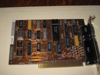
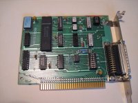
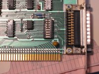
Does anyone know what the settings are for this 8-bit ISA serial card?

I think it's an IBM or a DEC version of the IBM card. There are two numbers on the card that look like potential model numbers:

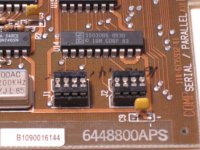
6448800APS and B1090016144

The 6448800 number gets google hits indicating that it's an IBM card. If I use the APS suffix there are some descriptions of it being a DEC card.

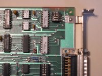
It has a 16450N UART and two 4-position setting jumper bridges. I'm simply looking to set it up as COM1 and LPT1.

Thanks, Matt
 

Attachments

  • IMG_0461.jpg
    IMG_0461.jpg
    52.4 KB · Views: 4
  • IMG_0463.jpg
    IMG_0463.jpg
    58.1 KB · Views: 4
Looks like a plain old IBM Serial/Parallel adapter for the 5170.

J1 controls the serial port. The top two positions shorted select COM1: 3xx addresses, IRQ 4. The bottom two positions shorted select COM2: 2xx addresses, IRQ 3.

J2 controls the parallel port. Top two shorted for LPT1 (3xx ports); the bottom two for LPT2 (2xx ports).

Note that you can simply invert a jumper block to change the setting.
 
thanks!

thanks!

Perfect - I'm already set up then as COM1 and LPT1.

Good tip on inverting the jumper block. I wondered what I would do to change it!
 
BUT, what about this one?

BUT, what about this one?

Ok, here's another IBM 8-bit ISA serial card, model 1503236XM

This model has two jumper blocks, J9-J12 at the top, and J1-J8 at the bottom. One for the IO port and one for the IRQ.

Also, there's one stray jumper in the middle of the card, J13.

If I follow a convention inferred from the configuration of the other card, if the top half of the pins are jumpered, it's set up as COM1. If the bottom half of the pins are jumpered, it's set up as COM2.

In the pictures attached, I have a card that is set up as COM2.

Can anyone verify that I'm right with these assumptions?

Also, what about J13? That seems strange. I'm not sure what a single, separate jumper could be used to configure on a serial card.

thanks again, Matt
 

Attachments

  • IMG_0464.jpg
    IMG_0464.jpg
    60.6 KB · Views: 2
  • IMG_0469.jpg
    IMG_0469.jpg
    59.7 KB · Views: 2
  • IMG_0470.jpg
    IMG_0470.jpg
    65.1 KB · Views: 2
Herb Johnson's retrotechnology site has the techrefs for the PC XT online. To save you a download, the 4-pin block is the port1/port2 select; the 16 pin block selects between RS232C and 20ma current loop operation and the single jumper when closed drives the 0WS (zero wait state) line on the bus when the card is selected. PCs and XTs do not have a 0WS line, but ATs do.
 
A current loop? O_O
There were serial cards that were capable of that ad not just adapters that hung off a serial port?
 
Back
Top