• Please review our updated Terms and Rules here

Macintosh SE 1MB - l crashed the logic board - Is there a chance?

Dallas_Green

Experienced Member
Joined
May 31, 2023
Messages
146
Location
Germany, Saxony
Hello community
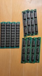
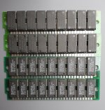
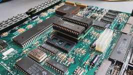
I just got this little beauty, the SE for my little collection and after some contact cleaning of the RAM modules and a little startup help to the old SCSI HDD it relay did get working again. Its prepossesor already cutted out the CMOS battery a while ago so that I was kinda happy not having any acid damage on the logic board found. So far so good.
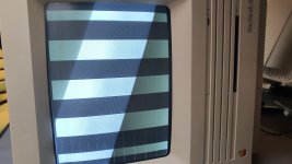
Then I just put everything back together and wanted to let it boot again to see whether everything was connected as it should. Everything fine, it loaded until the desktop and then, a wired sound appeard and a feeling like unstable current I thought, o lord - the ac cable wasn't plugged in properly but this wasn't the case. I switched it off and on again, having another try but it didn't boot anymore. It just showed the mosaic image on the crt but without any message and some strange noises on the speaker.

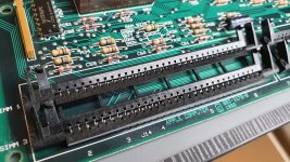
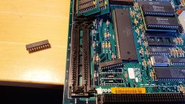
Then I saw what relay must have happened. One of the last screws laid under the mac, directly in contact with the logic board and its expansion slot. Guess it shorted some of the contacts of the connector and blew up some of its logic.

I'm so frustrated. It was almost working fine again and then, just because of a little headlessness I fried the whole logic board. 😭 Now it's not showing anything on the screen but the mosaic. No message, no beep. The speaker does make some little strange noises while powering up. It seems that it is willing to make a proper beep but can't. It sounds something weird.

Is there any chance to bring it back to life? It relay would be so sad for this logic board with it's awesome physical condition.

I checked of there are ICs overheating because I already determined broken ICs by this in other circumstances but here there are only a few chips getting warm, like the CPU and two chips next to the expansion slot


is there someone who can help me on that?
Thanks in advance,
Dallas

20240731_232545.jpg
20240731_232750.jpg
 
You have more problems than just a dead logic board. The retrace lines on the CRT are visible, this means that the tube is being driven way too hard, either because the analog board was jacked with or because the CRT is worn out.

I suggest going over the analog board and the power supply. If you've not recapped the power supply, there's more than likely leaked capacitors in there causing more issues, especially if they're the brown Nichicons. Also look for failed solder joints, especially on the connectors, those love to crack from the heat.

As for the checkerboard pattern, it could be several things, but I would start with the RAM, ROM and the octal buffers under the right most upper RAM slot (74LS245N x 2.) If you know where the screw was on the PDS connector, you can follow the traces on the logic board to what components they go to and one or more of those could be the culprit. But it's more likely a RAM or buffer problem.
 
Hello @GiGaBiTe
Yeah, I already saw those lines on the screen and knew that there would be more things to do in order to restore the SE completely. Recaping is not a big deal for me. I got quite used to that by now and have everything to do it (like de-soldering iron). Regarding the tube - well, its not unlikely that it became worn out over the years. When this SE was brought to me, the first thing I recognized was that I could still see parts of the image although the crt must have been switched oft for weeks. So I'm quite sure that it never will be get back to perfect shape. But in order to not making things worse, the analog board should be reviewed - you're right, thanks.

As for the logic I'll try to check components step by step. Unfortunately I don't remember where the screw shorted the PDS connector pins exactly. Sure, that would have been quite useful but such ideas never come into my mind in such shocking situations. So I'm going to exclude the components one by one from the list if possible suspects.

ROM: I have reader to get its content. Do you know if there is a reliable image reference somewhere with which I could compare the ROMs content to? Like minuszerodegrees.net has for IBM based computers?
RAM: At the moment I don't own another Macintosh for RAM inter-exchange or testing. Is there a other way to test the RAM? What I have read is that RAM issues should actually be displayed with an error code during POST.

Regarding other ICs to check on: Okay, I'll go for the 74LS245N first. Do you also think a replacement of the CPU could be a good idea? I saw that most of the traces from the PDS are going there and it's not complicated to get a spare part of it.
Just for asking: Are there like voltage regulators somewhere which also could have been damaged by the short?

Thank you very much for your help!
 
I did some research again and came to the conclusion that the mosaic/checkerboard pattern is being generated by the BBU, this quadratic socked apple chip. It accesses the DRAM directly every 4th CPU cycle in order to gain its information. If I take out the RAM modules one by one it can be seen that this doesn't work anymore or at least that less and less information is shown. Therefore I suppose that the BBU, RAM and the reading of the video information from the RAM does work. So it's not completely dead. Whats failing or missing is the reading/writing activity by CPU from/to the RAM. The most probable culprits would then be the bus transceiver chips (74LS245N) as well as the CPU by itself.

After having ensured the proper content of the ROM I'm gonna replace the 74LS245N then and if this doesn't help, I would go for the CPU. What do you think?
By the way: I had already a dead motherboard caused by such a 47LS254N transceiver ic which I investigated and finally fixed thanks to the help of @modem7, handled in this thread. :)
 
ROM: I have reader to get its content. Do you know if there is a reliable image reference somewhere with which I could compare the ROMs content to? Like minuszerodegrees.net has for IBM based computers?


RAM: At the moment I don't own another Macintosh for RAM inter-exchange or testing. Is there a other way to test the RAM? What I have read is that RAM issues should actually be displayed with an error code during POST.

The ROM routines to test the system RAM is very basic, and really only catches clearly bad RAM addresses. It won't detect marginal memory that may behave during a cold boot, but starts misbehaving later when it gets used and warm.

I would recommend getting a PC motherboard with 30 pin RAM slots, preferably a motherboard with a 16 bit bus, like a 386 SX to test modules. Motherboards with 32 bit CPU buses require four 30 pin SIMMs to make up the 32 bit bus, since 30 pin SIMMs are only 8 bits wide. With a PC motherboard, you can run an old version of Memtest to check the modules.

Regarding other ICs to check on: Okay, I'll go for the 74LS245N first. Do you also think a replacement of the CPU could be a good idea? I saw that most of the traces from the PDS are going there and it's not complicated to get a spare part of it.

I really doubt that the 68000 is bad, as I don't think you'd get anything on the screen at all. You can try replacing it if you want, but the PDIP-64 package 68000s are a royal pain to desolder, and you couldn't install a socket because it would block the PDS slot if you wanted to use it later.

Just for asking: Are there like voltage regulators somewhere which also could have been damaged by the short?

All of the power regulation stuff is inside the power supply. It's a SMPS, so you'll need to be familiar with how they operate.

You can check the voltages from the rear floppy connector on the machine, as all voltages from the PSU are present on that connector.

If I take out the RAM modules one by one it can be seen that this doesn't work anymore or at least that less and less information is shown.

You can't do this. The 68000 has a 16 bit data bus and requires two 30 pin SIMMs, which are 8 bits wide each to make up the full bus. Additionally, the Mac SE logic board has resistors that act as jumpers to set the amount of memory the system has installed. If the resistor configuration doesn't match the installed memory configuration, the machine won't work properly.
 
Hello @GiGaBiTe
You're absolutely right. The single SIMM modules were not supposed to work. I just wanted to see whether the behavior of the screen change because of the direct access of the video chip to the ram and it did.

I would recommend getting a PC motherboard with 30 pin RAM slots, preferably a motherboard with a 16 bit bus, like a 386 SX to test modules. Motherboards with 32 bit CPU buses require four 30 pin SIMMs to make up the 32 bit bus, since 30 pin SIMMs are only 8 bits wide. With a PC motherboard, you can run an old version of Memtest to check the modules.

Good idea. I've an AT here with witch I could test that. I'll report soon.
Nevertheless I think I've got some general doubts about the ram of the mac. I already read several threats about but it's still not completely clear to me.

As mentioned in the service manual actually all 1MB modules with a latency lower then 120ns should work. 4x1MB modules were installed before and I wanted to replace them with modules I took from a running AT mainboard but it didn't work. The mac failed completely creating the checkerboard screen with all the modules I tested. All 4x1MB, 70ns.

These for example. On the right the original ones which I took from the Macintosh and on the left those from the AT which I tried as an replacement and the mac didn't work with. Aren't they supposed to function as well? Do I have a misunderstanding here regarding the accepted SIMM modules?
20240801_220821.jpg
 
After having tried some combinations of SIMM modules, the Macintosh is now also failing creating a proper checkerboard image with the original SIMM modules. I already cleaned their sockets and contacts, exchanged them but with the same result. Little vertical stripes can now be seen on the screen and the wired sound (the attempt of a bong) while starting isn't there anymore. It seems that I've created now a second problem with the original RAM or at least with its connection to the PCB.

20240801_221005.jpg

Maybe, once I managed to bring the PCB back to live regarding the transceiver chips (or whatever it is causing), the mac would then be able again to report a proper RAM issue in order to let me know about the SIMM module which is failing now. Maybe. Nevertheless I'm gonna check these SIMM modules in the AT machine.

Regards
 
I tried now the original SIMM modules of the mac in the AT and it didn't even POST. So I guess there could be something wrong with them.

I then took the known good 8x 1MB modules from the AT and tested them on the mac - 4 by 4. But it showed then something else then the checkerboard image.

20240801_225038.jpg

Here are the SIMM modules from the AT I tested. The ones above are 1MB, so I just replaced them and good similar pictures to the one above.
20240801_231423.jpg

Then I tried the 256k modules from the second line of the foto, connected the resistor R35 again as mentioned in the service manual and got also not the checkerboard image again, just stripes, but quite clear.

20240801_230014.jpg

I have that feeling that the SIMM modules aren't compatible with the mac and those from the mac not with the AT. Is there something I'm missing? I'm confused.
 

Attachments

  • 20240801_230828.jpg
    20240801_230828.jpg
    1.6 MB · Views: 3
BTW: PSU voltages are ok so far. The only abnormality is the -12v rail which is just at -11.8 but i think this should be all right.

I checked moreover the ROM today and one of the chips is definitely broken. The reader says "bad PIN" and cannot gather it's content. So I'll try to get a replacement, but still having some doubt about the right EPROM here.
 
As mentioned in the service manual actually all 1MB modules with a latency lower then 120ns should work. 4x1MB modules were installed before and I wanted to replace them with modules I took from a running AT mainboard but it didn't work. The mac failed completely creating the checkerboard screen with all the modules I tested. All 4x1MB, 70ns.
View attachment 1283954

The Mac SE is extremely picky about the memory it will use. Generally, you need 8 or 9 chip SIMM modules, the 2 or 3 chip modules are hit or miss if they will work or not. IIRC, it's something to do with how the memory columns and rows are laid out on the modules, which is different between the 8/9 and 2/3 chip SIMM modules. Those extra tall memory modules may also be problematic and cause fitment issues.

I had this problem on a customer's Mac SE I was working on. I had to end up ordering some expensive 9 chip memory modules and the machine behaved fine after that. My own Mac SE FDHD has a 68030 upgrade installed, and the upgrade board has its own memory slots, which are far less picky about the memory it will take.

Something else to consider is you have the really terrible memory slots with plastic clips. Those things are known to be problematic. You may want to source better memory slots with metal tabs instead. Your slots don't look right, like parts of them are broken off, but it could be the angle and lighting making them look weird.
 
Generally, you need 8 or 9 chip SIMM modules, the 2 or 3 chip modules are hit or miss if they will work or not

Well, I surprisingly had another pair of SIMMs with 9 chips. But the result isn't checkerboard like either.
 

Attachments

  • 20240802_105228.jpg
    20240802_105228.jpg
    3.1 MB · Views: 4
  • 20240802_105122.jpg
    20240802_105122.jpg
    1.3 MB · Views: 4
Your slots don't look right, like parts of them are broken off, but it could be the angle and lighting making them look weird.

Guess it's just the angle. In fact I barely have seen sockets in such great conditions. Other mainboard are often much worse.
Is there a chance to measure if the traces a really coming through the socket? I did a impedance measuring between the socket solder points and the contact plates of the SIMM modules and ended up with 0 Ohms, but not sure whether this is a meaningful thing to do.
 

Attachments

  • 20240802_104540.jpg
    20240802_104540.jpg
    2.6 MB · Views: 6
With the alternating white and black columns, it looks like you have a broken bus.

I saw you may be having issues with one of the ROMs, which would definitely cause this behavior. As could a broken 74LS245. You could try swapping the positions of the buffers and see if the columns of white and black change position.

Guess it's just the angle. In fact I barely have seen sockets in such great conditions. Other mainboard are often much worse.
Is there a chance to measure if the traces a really coming through the socket? I did a impedance measuring between the socket solder points and the contact plates of the SIMM modules and ended up with 0 Ohms, but not sure whether this is a meaningful thing to do.

You can check the pins to the nearest trace and see if there's any resistance or the trace is open. The reading should be as close to 0 as possible. I think the address lines go to the BBU/68000 and the data lines go to the 74LS245 octal buffers.
 
Agreed. So I'll try to solve the rom issue and bus first before I go further on the ram topic.

Speaking about the BUS I found this schematic. Seems that there are a way more possibilities of culprits...

1722590386440.png
 
While that looks like a lot, you can remove the SCSI, SWIM and SCC from the logic board and still have a system that will boot, just not do anything once it looks for a startup disk. I don't remember if the VIA is critical or not for the system to boot due to the RTC.

The critical stuff is the BBU, ROMs, RAM, 68000, muxes and buffers. If you have a dead BBU, you have a big problem unless you have a spare. Nobody has reverse engineered that chip and made clones yet as far as I'm aware.
 
Hello @GiGaBiTe
I managed to create the rom adapter now and had a first try, without any better results unfortunately.
Just to make sure that I created the rom the right way: I took the rom file from Macintoshrepository.org (256k SE FDHD), used the rom splitter from 68kmla.org and created successfully 2 files, 128k each, which I then burned to 2 winbond W27C010 chips as suggested. Now I'm doubting whether there is something still wrong here, also, because the last command in this mentioned thread says that they couldn't get any working rom either out of this adapter board.

Is there something I could have done wrong or someway to doublecheck it in order to ensure that the rom is now ok? Unfortunately I do not possess a second SE to test it there.

Thanks in advance
Dallas
 

Attachments

  • 20240820_170657.jpg
    20240820_170657.jpg
    2.8 MB · Views: 7
  • 20240820_170428.jpg
    20240820_170428.jpg
    1.5 MB · Views: 7
  • 20240820_170448.jpg
    20240820_170448.jpg
    1.6 MB · Views: 7
Yes. It's also marked on the adapter board. I wrote the rom one by one and seated them right after writing.
Maybe I'll go then replacing the 74LS245 chips precautionary. I have this feeling that without a second SE this is going to be a long way^^
 
Hello
These days I had some time left to get further on my retro projects.
I replaced both 74LS245 but didn't get any better results. Still checkerboard without anything.
While that looks like a lot, you can remove the SCSI, SWIM and SCC from the logic board and still have a system that will boot, just not do anything once it looks for a startup disk. I don't remember if the VIA is critical or not for the system to boot due to the RTC.
Well, it seems that I have to go further in that list in order to exclude further culprits from it.

Meanwhile I had the chance to buy a second SE on ebay - small money, unfunctional as well. But maybe this will help by exchanging BBU and ROM chips for further component testing.
Also the ROM thing and my self made ROM adapter can be verified then. Let's see...

I'll keep you informed - also for proper documentation.

Regards
Dallas
 

Attachments

  • 20240914_161518.jpg
    20240914_161518.jpg
    3.3 MB · Views: 7
Hello
These days I had some time left to get further on my retro projects.
I replaced both 74LS245 but didn't get any better results. Still checkerboard without anything.

If you have the RAM installed like you do in the picture, then there's the reason for the checkerboard.

You need to have memory modules installed side by side, not up and down. The way you have it in the picture will only have half of the memory bus.
 
Back
Top