• Please review our updated Terms and Rules here

NCR 8707 (aka NCR MODEL 3279 PC8) needs some help

Wobblestone

Member
Joined
Jul 22, 2023
Messages
29
Hi!
I just purchased a giant computer, a NCR 3279-0202. It is a 286 with (I guess) 640kB of RAM and a big, fat ISA-card, which contains (I guess) serial, parallel and some graphics stuff.
The mainboard is this one:
In this forum, there was already a thread for this mainboard:

My problem is now, that the mainboard does not work.
As I got it, it has a dead short on the +12V rail and -12V rail - the common dead capacitor thing. So far I just removed the shorted caps from the mainboard, but I did not replace them yet.

In order to test the board, I removed everything except the post code card. As PSU I used my trusty modern power supply, which works perfectly fine.

After switching it on, it posted, but stops always, depending on the clock speed:
-) If SW2 is set to 8 MHz, it stops at post code 0807
-) If SW2 is set to 6 MHz, it stops earlier at post code 0506
In both cases it beeps 5 times short.

I don't know how to proceed. Does somebody know, what these post code mean - and what 5 short beeps mean?
Since it shows signs of life, I assume that the CPU works and maybe most other parts too. But of course I might be wrong.
 
After switching it on, it posted, but stops always, depending on the clock speed:
-) If SW2 is set to 8 MHz, it stops at post code 0807
The POST card is showing you two POST codes, 08 and 07. One code is the last code received, and the other is the code received before that. Quite misleading. Only the last POST code received is relevant.

If your POST code matches the 'Example of a modern POST card' one pictured at [here], then 08 is the last code received, the relevant code. And that makes sense because we expect that 08 was sent after 07.

-) If SW2 is set to 6 MHz, it stops earlier at post code 0506
0506? Based on the order of "0807", I expected "0605".

I don't know how to proceed.
1711763242703.png

Does somebody know, what these post code mean - and what 5 short beeps mean?
Ideally, the user/technical manual, if it can be found, contains that information.
Be wary of other sources (i.e. non-authoritative) of that information. I have started authoring a web page on that subject, at [here].

Since it shows signs of life, I assume that the CPU works and maybe most other parts too. But of course I might be wrong.
The power-on self test is starting. Are you in a position to try a Supersoft/Landmark Diagnostic ROM in the BIOS ROM socket?
 
Hi!
Thank you very much for your help!
My post code card is exactly the one, which you've mentioned above. And now I finally understand, how this codes work :)
0506? Based on the order of "0807", I expected "0605"
Of course you are right....

I resocketed and used some Deoxit on the sockets and the ISA slots, without any change.
So far I could not find any information for this mainboard, except of the thread in this forum and the retro web. But no manual, nothing.

Are you in a position to try a Supersoft/Landmark Diagnostic ROM in the BIOS ROM socket?
Yes, I am. Based on your response, I already tried the 27C256 EPROM, which I used for fixing my IBM 5150.
But this machine remained dead after replacing the ROMs. Since I did/do no know, which one to replace, I've tried both. But the mainboard remained completely dead, no beeps, no post codes.

Does the Supersoft/Landmark, which worked on the 5150 also work on AT machines with 80286, or is there a special version available/necessary?

Some of the post code/beep code lists in the net indicate, that 5 short beeps mean that the CPU might have a problem.
Would a system with dead CPU even give ANY post codes?
 
Does the Supersoft/Landmark, which worked on the 5150 also work on AT machines with 80286, or is there a special version available/necessary?
There is an XT version of the diagnostic, and an AT version.
In the 'ROM Images' section of [here], you see me using "Uses PC/XT version" and "Uses AT version".

Some of the post code/beep code lists in the net indicate, that 5 short beeps mean that the CPU might have a problem.
Would a system with dead CPU even give ANY post codes?
Assuming that for your BIOS, 5 short beeps does correlate to 'CPU fault', maybe the CPU is only partially faulty.
 
Hi again,
modem7, you are my hero (y)(y)(y)

With Supersoft/Landmark for AT I finally got a picture and a hint what was wrong: It told me "16K Critical Memory Region" failed. I then removed the entire RAM bank 0.
My RAM tester told me, that 10 of the 12 ICs were faulty. 10 of 12!!!

Luckly I had spares of 4164 and 4464. Using these it was possible to even use the original ROMs to boot. But it still gave me errors, indicating the the other banks were faulty too.
So I had to remove/socket/insert all other RAMs too. From 30 RAM ICs, about 25 were faulty. What a carnage. I really don't understand what was going on here.
Replacing all RAMs with known good ones was still not enough. The system still reported a RAM error.
It turned out, that A5 (Pin 7 of 4464) on the second half of Bank 0 was not connected. After connecting this, the system even booted to DOS.

Resoldering 24 ICs (and life == cooking, maintaining the garden and so on) took the entire day, but finally it looks good.

Tomorrow (hopefully with more time), I'll assemble the machine and try again. Then I'll post a final conclusion here, maybe this might help somebody else with such a machine.
 
Hi Wobblestone,

Congratulations on this excellent purchase! I remember it's a truly beautiful model!

I hope yours was made in the US? I think they must have had much higher PCB assembly quality there compared to what I have seen on my NCR mainboard.
I only have the mainboard which is terribly faulty.

I may attempt to repair it one day but I am afraid it's suffering from broken traces, mine was a terrible soldering job from the factory.
It suffered from terrible DMA problems I remember but later it developed even more troubles.
It's really a shame that the PCB was so bad.

Wish you lots of fun and enjoyment from using this tank of a PC.
It's very satisfying after you repaired it yourself!

Kind regards,

Rodney.
 
Hi Rodney,
that's a pity, that your machine makes so much troubles. Mine seems to be "Made in Germany". The soldering is perfect (except of the parts, which I had to solder.... :cool:).
The machine works now fine. Even the 5.25" disc drive works fine. The hard drive is one of the most interesting parts - it is a monster. 5.25", full height. An Imprimis 94155-85P.
So far it does not yet do anything. It would be awesome, to hear the sound of that drive spinning up. But I would also be satisfied having a XT-IDE in the machine.

Do you have the same mainboard as me (see the link above on retroweb)?
If you need some photos of parts of the board, just let me know.
I will soon upload my bios roms to the retro web.
 
Hi Wobblestone,

Indeed, I was very hopeful at first that I would be able to repair my NCR board however it was somewhat of a disaster. 12 Of my DRAMs were directly soldered into the board and were all faulty. So I proceeded to desolder them and put sockets in. The RTC was desoldered by someone, The CPU socket was damaged, no BIOS ROMs present, broken keyboard connector. Anyway I fixed all the issues, put a PLCC CPU socket and 286 CPU in, put working DRAMs and a original BIOS on the board. I was able to revive the board but I never got DMA and the floppy drive to function. So a sound card also didn't work on the board because that also needs DMA. I needed a lot of resets to get it to POST and boot. Possibly there had been issues with the PAL chip doing data byte conversions because the symptoms look like that when I look back on the matter now. Also it could be located in the DMA control/refresh generator circuits because sometimes during floppy access it would develop parity interrupts and not during any other functions of the system. Anyway it was a long time ago when I tested this board.

After doing my project to redesign the 5170 I have more experience about the function of this mainboard so probably I can repair it by comparing it to the 5170 and tracing back all the part numbers and tracing the functions throughout the logic path. Everything can be repaired, the only matter is to have enough time for it.

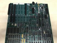
The worst thing about this mainboard of mine is the terrible warping of the wave solder job by the factory. Maybe this board was a manufacturing failure and taken home by an employee, or found in a clearing out of a building, who knows. In the batch I also got 2 Decision Mate V mainboards which is also a great looking machine with beautiful design style. So this batch of 3 PCBs contained all NCR PCBs. The warp in my board seems to be the worst around the ISA slots where I estimate it is around 1.5 mm of a warp in the board. On the corner around the RTC the bottom of the board looks affected by some kind of chemical. Maybe someone used some aggressive solvent to clean away flux. If there are bad contacts in the PCB it is easier to fix, however if there are contacts which are intermittent in being broken or conducting, that will be more difficult. The board looked mistreated and not carefully kept, which is always a risk when buying off Ebay.

Anyway, to be honest when I saw photos of the PC-8 the thing I loved the most was the design, really beautiful. If I had the case with my mainboard I would put a lot more effort into restoring it. Like maybe desoldering the ISA slots and trying to slowly warm up the board to reduce the bulging shape and press it straight. Having the whole PC would have been much better.

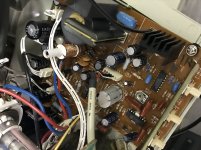
It's good that you removed the 12V tantalum capacitors because they can give off a big fireworks if they go short while powered on and the debris is potentially so hot almost like welding it can burn into plastic surface if there is any in the neighborhood. It can even be dangerous for a person's eyes if you are near the caps when they blow. One time I saw an IC explode off a mainboard during a repair that was also pretty spectacular and funny. But that mainboard was from around 2002 I think.

My mainboard has assembly numbers 017-0037571 A and 017-0037572 A, apparently it's a 6/8Mhz board which is typical with those early ceramic 286 chips same as the IBMs. The schematic number is 017-0035012 F. The assembly number can probably give an impression of which board is older or newer. I think yours is probably newer so the solder job was much better.

Indeed, do upload the BIOS to the retro web if you have the chance, this can interest a lot of enthousiasts who are fans of NCR computers. Anything that can be preserved, is worth it.

I love old harddisks who are big and heavy and especially if the head motor can make a lot of noise which is just cool to hear the seeking sounds.
What I understand is that a lot of old MFM harddrives are difficult if not impossible to get them working, but I suggest not to give up until you are sure it can't be revived. There are some youtube videos by Adrian Black where he works on MFM drives, you can look at how he does the work to test them maybe it can give you some clues how to try it. But if you get it to work, the first thing you should do is copy the DOS folder and other folders, which can possibly give you the original install files of the machine. The chance of getting it to work is pretty slim because these drives are usually in bad condition and unable to work. I own one DEC SCSI drive which is 5,25 inch and 1.8GB, which still works. It's pretty cool to feel the vibration of this unit when you touch it, really a beast of a thing!

Anyway enjoy the PC-8, do you have a cool CRT to match for a setup?
I recently connected my PC to a CRT using an old ATI small wonder card. The composite CRT is color unfortunately but it has a green button on it. :)
I plan to design a recreation of an old IBM 6845 based graphics card which can put out a composite signal for a CRT. It should not be too expensive and won't take long to make one. I want to have the original functioning card so I can test out software and games compiled specifically for those old cards. Also such a card can be helpful to diagnose problems while repairing old mainboards. Sometimes the mainboard can't start a VGA BIOS ROM but it is able to output errors to a screen on a old graphics adapter. I have had such experiences for example if the RTC has faults.

Kind regards,

Rodney
 
Last edited:
WOW!
I am just a beginner and I need lots of external knowledge (like this forum) to repair such computers.
On this mainboard 3 tantalums were broken: One had exploded already and I just found the lower part. Two others (on +12V and -12V) looked fine, but were shorted.
It's a pity... I liked the green color of that caps :alien:

The harddrive finally spun up, after cleaning it and the connectors. Also the head is getting "unparked" and can then move easily. But except of moving, it does not do anything. Well, i'll keep it inside the machine, but for now I put the XT-IDE in it. With that the machine works great and boots to MS-DOS 6.22.

Anyway enjoy the PC-8, do you have a cool CRT to match for a setup?
Well... I'm not such a fan of CRTs. They are big and heavy and you normally don't find schematics.
Of course I have the usual models like a Commodore 1081, 1084 and 1702. And some old apple CRTs for Macs. A couple of years ago, I pulled an apple studio display with 21" out of the scrap. This monster weights about 35kg and is huge and - of course - it worked and still works.
For EGA/CGA I normally use a RGBTOHDMI or... an Eizo 8060. This has by far the best picture quality of all screens I own. It should be a little younger than the NCR, but not much. I owned such a monitor back in the days. They were the best and still are. And now they are incredibly rare.
 
21" is indeed very large and extremely bulky, I feel so too. When I moved a few times I have only been able to save and keep a few smaller CRTs like 11 or 12 inch similar to the 1084 type of model, one is an Ancona. Even those are still quite heavy.

Today by coincidence I found and bought a green AOC 12" CRT for a reasonable price. It has a 9 pin connector which is kind of rare here and still looks a little modern even though it's from 1987, so not bad, at least it's lighter color plastic and not black. I think it will look nice on top of a tank PC. This will be my only 9 pin monitor, I never had one of those before so I am glad to have at least one for testing out legacy graphics outputs, hopefully it still works after I get it delivered.
 
The harddrive finally spun up, after cleaning it and the connectors. Also the head is getting "unparked" and can then move easily. But except of moving, it does not do anything. Well, i'll keep it inside the machine, but for now I put the XT-IDE in it. With that the machine works great and boots to MS-DOS 6.22.
Hi Wobblestone,

I recently saw a youtube video by Adrian about powering on a MFM drive.
What he also mentioned is that when you power one up, that it's important to keep the drive with the controller it came with.
At least, it is apparently that way with drives which are compatible with 8 bit systems (first PC and XT models), because those are usually formatted by the software on the controller itself. Basically what I understand is that the drive itself is much like a floppy, meaning there is no intelligent controller on it.
The controller is then on the MFM PCB and controls the MFM drive much the same as controlling a floppy (stepping the tracks etc).

Maybe you can watch his videos and get some idea if there is a chance of getting the harddisk to work.


These days most of these drives have gone bad, but you can never know, maybe yours can still work.

I love the noise these drives make especially when seeking.
It's really a great experience to me to hear the drive working, and I have fond memories of my school days working with some Tulip PCs which just sounded cool when the drive was working inside.

By the way, I have been desoldering some ISA slot connectors from the NCR mainboard. Maybe later I will desolder the PCB completely and try to gently straighten the PCB more and more with heat treatments and applying some gentle pressure and let the PCB settle for a long time. I could make it a restoration project to try to make the PCB perfectly straight and in good condition. Then I only need to find if there are broken traces. If you like if I have information later about the mainboard, which I will need anyway, I could update you with more details since you own the PC.

Kind regards,

Rodney
 
I found and bought a green AOC 12" CRT for a reasonable price. It has a 9 pin connector
Hi Rodney, what do you mean with 9 pin connector? Do you mean that CGA/EGA/MDA connector?
If yes, I agree, that these are quite rare already. But I mostly use a RGBTOHDMI. If this does not work, then I use my Eizo. If the computer and graphics card works, then the Eizo shows something. I don't trust the RGBTOHDMI that much ;-)

I know all videos from Adrian. He is my favorite retro youtuber. This particular video is (again) a source of important information for me. Your idea of using that knowledge for the big-fat harddrive from the NCR is great. I'll try that once I have time.

Right now I'm working on a Commodore PC40-40. It was the dirtiest machine, which I ever purchased. But based on what i learned from reparing the NCR, it was then easy to repair it too.
I'll create a new thread for that - not because I need help, but to document what I found out.
By the way, I have been desoldering some ISA slot connectors from the NCR mainboard. Maybe later I will desolder the PCB completely
You did/do what!? Desoldering an entire PCB!? What a monster job will that be! I'll keep my fingers crossed, that at the end you and the poor mainboard will be winners (y)
Of course keep me updated :)
 
Hi Rodney, what do you mean with 9 pin connector? Do you mean that CGA/EGA/MDA connector?
Hi Wobblestone,

Exactly that is what I mean. I received the monitor this week in the original box it came in in 1987, and after opening the back cover I saw zero dust inside, it looked like fresh from the Taiwanese factory in 1987! I suspect this monitor was hardly used and kept inside the box for the most time. What a lucky find, I am quite happy.
Even the stickers from the plastics company were still inside the shells, which is nice.

Using a EGA/CGA/Monochrome MDA screen with the 9 pin connector is apparently not completely straightforward. It uses normally the PC BIOS to generate the screen which is useful for debugging a mainboard which is not initializing the VGA because of some problem. I have had experiences before when you can see a message on the CGA screen telling the error. I have tested a ET3000AX card which has VGA and 9 pin output however I was not able to generate the screen using any of the 4 dipswitch combinations available. So I took my ATI Small Wonder 8 bit card and only a small tweak of the jumper resulted in the full BIOS screens shown and after DOS is booting it continued to show the screen. So this was the better choice of card from what I have. At first I was getting ready to do repairs of this and planned to look for a relevant video from Adrian, who we know is quite versed in looking at CRTs, however I quickly found that the picture was fine. Just some minor tweaking on the focus and I adjusted the deflection yolk angle a tiny bit to get it nice and straight. This CRT is nice and small, weighs not too much so it's convenient to handle.

Yes, Adrian always gets a lot of donations thanks to his channel work, and also I suspect that in the Portland area there is an active community around who are enthusiastic about vintage computers. Adrian is always finding new stuff and possibly from some sources selling vintage stuff in his area. It just seems like a good place to live when it concerns our hobby. So he has been able to look at and test a good number of those MFM harddisks I believe. His experience is also useful for other hobbyists.

Commodore PC-40, very cool find as well! I understand from what I have seen in terms of photos that Commodore used a lot of chipset integration in their PC lines which makes sense from a cost perspective of course. Hopefully your chipsets are okay then it should be possible to get it to work. I have seen some examples where a chipset IC had died. I look forward to reading about it, sounds good!

Yes, I removed 4 ISA slot connectors which I needed for my old 486 board which I took them from before for one of my own prototypes. It was not too bad to desolder them, thankfully my desolding iron has enough thermal mass and suction capacity. Doing this whole desoldering job will be a lot of work, maybe it will occupy a whole evening I think. I feel the poorest thing that happened to this mainboard was that terrible soldering job in the factory. Indeed desoldering everything is another small abuse but it's the only way I know of to restore it to a reasonable state. If I do the effort later to repair this PCB, I would only do that in combination with straightening the PCB so in the end I have a nice looking straight mainboard, and in working condition that would make me a lot happier about it. :) I saw my old notes about the repair which tells me that the troubleshooting had taken me quite a long time until I gave up on it. Anyway, I know a lot more about how the early ATs functioned which can help me to pinpoint where the problem is coming from more clearly.

If you do decide to make that Commodore thread, I look forward to seeing it!
 

Attachments

  • Img_3424s.jpg
    Img_3424s.jpg
    228.7 KB · Views: 4
  • Img_3447s.jpg
    Img_3447s.jpg
    546.6 KB · Views: 4
Hi Rodney,
the Commodore Thread exists already:

For diagnosing XTs and ATs I learned, that you need an EGA/MDA/CGA graphics card. Therefor I keep one on hand, which works very well. It helped me a lot reparing IBM 5150, 5160 and now these two ATs (NCR and Commodore). Without this forum and the Landmark ROM, it had been impossible.

Which desoldering iron do you use and at which temperature do you work?
 
Hi Wobblestone,

Great, I will check out your thread now!

I have owned a poor desoldering iron for years, a Aoyue, which I had modified to take a Hakko desoldering tip which extended its life beyond a few weeks.
The original tips "melt" after a few hours of working with them. So I continued working with Hakko tips, and when I ran out of those, I found some old weller tips which I used.
I "screwed" the weller tips into the used up Hakko tip base which lasted for weeks of regular work.

Then finally it completely died because the element was broken and I have been without for a few months, using only hot air to take out ICs.

Recently I bought the Hakko FR-301(-020). I always set it to max, which is 500 degrees celsius.
It has tackled any desoldering job, usually between one and two seconds of heating the pin is enough to take out all the solder from a pin.
I desoldered the ISA slot connectors in one go without refreshing the solder joints first.
So I am quite pleased with this Hakko. In the past I used a old Hakko model in my repair work for my job which also worked great.

This new Hakko is a little noisy which makes it less suitable for using when other people are sleeping. ;)
 
I think I want that Hakko-Thing too.......... :love: although it's quite expensive. But since my next birthday will be soon (in November), I should make myself a gift :p
 
Yes, this one is definitely the best I have tested so far. These days I am doing a lot of desoldering.
This hand unit Hakko is actually a lot cheaper compared to other models because it is smaller and more simple in construction.
It's really good construction quality, great materials and has a strong pump inside.

A tip if you decide to buy one, if you suddenly notice that the suction is a lot less, some debris may have gotten into the membrane pump.
I got some tiny solder balls in there somehow yesterday which got past the filter I think by accident while cleaning it.
So I opened the pump housing and cleaned it, which made it work like new again.
After noticing this I am more careful from now on around the area which goes to the pump.
 
Thank you for these helpful facts (y)
It is not so easy to buy this device here in Austria. There are a few online shops, which I don't know. Well, so far my cheap ZD-552 works fine. I just need to be patient, until I find a good offer for the Hakko.
 
Back
Top