• Please review our updated Terms and Rules here

Need Plasma Voltages for NEC Powermate Portable SX - Can anyone measure them at all please?

cj7hawk

Veteran Member
Joined
Jan 25, 2022
Messages
1,130
Location
Perth, Western Australia.
Hi all,

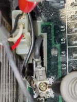
I think I posted in the wrong forum section previously. I'm repairing a Powermate Portable SX and the Plasma screen stopped working. Is anyone able to measure the voltages from the ground terminal near the Plasma power plug in the ISA slot bay and tell me what they are?

There are 3wires and they could all be up to around 200v DC, so be careful when measuring. You don't need t unplug the display, just measure from the back of the plug itself to the ground terminal spades nearby.

There is a black, a white and a red wire. I need all three with reference to ground. As seen in the two pictures below.
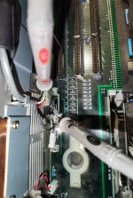
IMG_20231216_180148 (Small).jpg

Close up.

IMG_20231216_180210 (Small).jpg

I'm getting 5v on Black., -183v on White and -188v on Red ( 5v lower than white ).

I can see all the other signals getting to the display, so am unsure as to why it is not working. I'm Not sure of the display pinouts beyond the video signal and the contrast knob, so if anyone has any schematics or details on the displays in these models, that would also be appreciated. I can figure out the vide signals, but I'm not sure which is the enable line.

Also, my CMOS is reset... If anyone knows where I can get a disk image or the programs to reset it that would also be greatly appreciated -

Thanks and Kind Regards
David
 
-195 V on red, -190 V on white, 5.25 V on black, contrast wheel maxed out

How were the caps in yours? I haven't opened my PSU yet
 
:( That means my PSU is working, and I never touched the Plasma display before it stopped working. I wonder if I lost a line from the ribbon cable?

My PSU was pretty bad. It's in two parts - the lower part rectifies the AC into 300vDC ( or thereabouts - I'm on 240AC here ) and pushes it into a DC connector which goes to the top board that powers the machine. The remainder of the bottom board is the High Voltage PSU, which drives out the voltages you've mentioned for the plasma, It has a 10uF 250V capacitor on it that I need to look to change in the future, but it seemed like it wasn't too bad. I suspect it has very little ripple current.

But the output filters on the top board were ALL bad. One was visibly bad - it was blown at the top and leaking, and smelled really bad when the PSU was running. Also, I heard a sound a bit like Chirping if left on too long.

Then the others were all bad when I removed them, showing signs of leaking at the base and being in the early stages of preparing to let the magic smoke out... Every single one... I noticed the residue when I removed them. They are mostly 1000uF or similar. The PSU was pretty good except for the electrolytics... BTW, I am one of the people who doesn't believe in recapping unless the caps show signs of distress or are getting too warm (as checked with thermal camera ), but in this case, it was absolutely necessary.


Here's your complete list of what is in there. Diameters mentioned. Length not recorded sorry, but may be an issue for the two mains caps...

Upper PCB.

Power filters.
10v 1000u 10mm x 2
16v 680u 10mm x 2
10v 1000u 12.5mm
10v 2200u 16mm x 2

Smaller caps
10v 470u 8mm
16v 56u 4mm
35v 56u 6mm (-12v via 7912 )
16v 390u 10mm (-5v via 7905 )
25v 22u 4mm


Lower PCB ( with the mains caps and the Plasma PSU output )
250v 470u 26mm x 2 ( mains DC rectification ) - A bit tight on space here.
25v 47u 4mm
10v 47u 4mm
250v 10u 10mm <--- Lots of space around this, but I haven't found a supplier yet. Clearly it's for the -190v line.
16v 56u 4mm

I went low-ESR and mostly aimed at 50v or 25v where possible to get something that will last longer. There is clearly some strain current-wise on the 5v and 12v filter caps... Also I couldn't find 680u locally, so wen't 1000u.
 
Thanks for the capacitor list. My PSU doesn't appear to have any problems, but after what you describe and my experience with other Japanese capcitors of that era it might be worth having a look.

How would you explain the 7V difference? Do you think this is causing your display not working? Have you checked the DIP switches and does the computer boot otherwise?

EDIT, regarding your CMOS settings see this and later posts: https://forum.vcfed.org/index.php?t...ext-too-big-to-fit-help.1244601/#post-1354553
 
Last edited:
All working again :) Seems I managed to disable the Plasma panel. I checked at the panel and all signals were arriving, but I couldn't figure out which was enable, so I went back to check the switches until one flipped a state at the panel, then reassembled and it all come sup - Nice clean panel.

Now I've ordered a Sound Blaster 16 to add to it - :) I'll need to add some internal speakers though as I don't want to have to carry speakers around.

Anyway, in case it assists anyone else, here's the panel pinouts that I figured out with an oscilloscope... In case anyone has issues or wants to connect such a panel to a modern display card.

1 +5V from chassis. ( not to be confused with black wire. There should be no connection between them...
2 +5V from chassis. ( DIFFERENT from other grounds )
3 Enable signal ( High 5v = enable )
4-24 - GROUND
5 Vertical Sync Negative
7 Horizontal Sync Negative
9 Blanking ( Both ) LOW=Blanking.
11 Clock (25.125 MHz)
13 Unknown
15 Video0 (TTL-Blue?)
17 Video1 (TTL-Green?)
19 Video2 (TTL-Red?)
21 Unknown ( Video3 ? )
23 Unknown.
25 Unknown.
26 Unknown ( Possibly linked to 27 in some models? I've noted some displays have another voltage here )
27 Unknown ( Possibly linked to 26 )

With this, my final voltages on-panel were

GND - To Panel Chassis. Should be 2 ground wires.
Black (in connector) +5v
White - Minus 193 (-193) volts
Red - Minus 198 (-198) volts. Should be exactly 5v different from white. I think this drives logic on the panel.

That's about it. It's a nice panel to look at, and Windows 3.1 is right at home here. With 2Mb, it could probably run Windows 95 too,

Switch 1 on Bank 2 should be "shorted" or "ON" for this to go "High" shortly after power-on. The video signal is always present, so the Enable signal could be shorted to 5v if you wanted to connect this panel to VGA display, and I found my vertical was 70hz and my horizontal 31.5KHz. The video signal is TTL level, so you'll need to do something about a VGA input to bring the voltages up - possibly a high speed comparitor or op-amp with a cut-off.

Plays solitair nice...
 
Back
Top