• Please review our updated Terms and Rules here

Please help with WD1770 FDC for 5.25 Inch drives

pconst167

New Member
Joined
Aug 8, 2024
Messages
5
Please I have been trying to use the WD1770 FDC for more than a week now without success. I have tried multiple drives and multiple IC's.

The main issue is that when I issue STEP or SEEK commands, and I look at the STEP line on an oscilloscope, it stays around 0V.
I never see the negative pulses that are supposed to come there. I am pulling my hairs trying to understand what I am doing wrong.
I even tried adding a pull up resistor thinking maybe the STEP line is open collector, but it makes no difference.

I am powering the IC from 5V USB, and the floppy drive has its own wall power supply. I thought maybe the grounds were not connected together, but
I am pretty sure they are inside the floppy drive. All the even pon numbers are ground and I assume the drive itself connects the 12V and the 5V grounds together inside it?
But I am not even sure that is the problem. Why, would the STEP line never pulse? I have tried 4 different WD1770 but the behavior is the same.

Please, if you can, give me a hand. Thank you so much!

Paul
 
Post a schematic of how you have wired it up? It is much easier to spot any errors (if there are any) that way.
 
I am powering the IC from 5V USB
So, a WD1770 chip, not a WD1770 based controller card.

The main issue is that when I issue STEP or SEEK commands, and I look at the STEP line on an oscilloscope, it stays around 0V.
I never see the negative pulses that are supposed to come there.
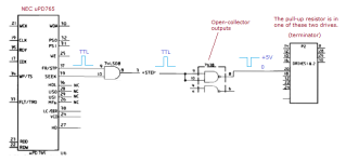
The data sheet for the WD1770 chip shows positive-going step pulses. Those will be at TTL levels.

1723254857995.png

Certain circuitry after the WD1770 chip inverts the step pulses.
Negative-going step pulses are what are on the cable between the controller card and 5.25" drive.
The situation will be like what goes on in the floppy controller that IBM supplied in the IBM PC - see below.

1723254692615.png
 
Hi all.

I do have inverters at the outputs. I changed the drive and re-wired everything up, and it works now. But I don't really understand why!
The weird thing now is that I disconnected one of the drives (its a double drive system), and I am using the drive without terminators, and yet it works.
How is this possible? If anything, the other drive which had terminators should have worked. Yet the drive that didnt work was the terminated one.
The unterminated drive works. Why?

I have read today that some or most of the odd pins or grounds are not actually connected? I was using only one pin connected to ground, and perhaps it was unconnected.

I will check.

ALso, would it make any real difference to use OC inverters? I am using 74HC04 which are not OC. What difference would using 74LS06 which are OC would make?

Very weird...
 
ALso, would it make any real difference to use OC inverters? I am using 74HC04 which are not OC.
The weird thing now is that I disconnected one of the drives (its a double drive system), and I am using the drive without terminators, and yet it works.
How is this possible?
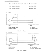
See the diagram below, taken from the 'Tandon TM100 Operating and Service Manual'.

What is the terminator there for:
1. Reduce the effects of long cable runs (the cable starts to act like a transmission line), and
2. Act as a pull-up resistor for the open-collector driver/buffer (7416, 7438, etc.)

Your cable run will be short, and you are not using an open-collector driver.

ALso, would it make any real difference to use OC inverters?
When the engineers were choosing the method of {open-collector driver with pull-up resistor on the drive}, they no doubt were considering that the cable length could be as long as 10 feet.
1723270192041.png
 
Hi there.

So I found something.

This is a dual drive setup. The IDC cable goes to both drives. One drive only is selected.

If I removed the IDC from one of the cables, it works. If both drives are connected it does not work.

I don't see why that should be...?

Is it to do with the non open collector inverters I am using?
 
Not much. It says it can drive one TTL load and 3 LS loads.
Are the drive inputs TTL or LS in general?
My drives are: TEC FB-501
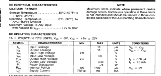
And the drive datasheet says this, which seems to say the inputs are LS equivalent, so in this case it should not fail with 2 inputs total?
1723303521986.png


The WD1770 datasheet says:
1723303673639.png

Does this mean it generates 1.6mA per output max?

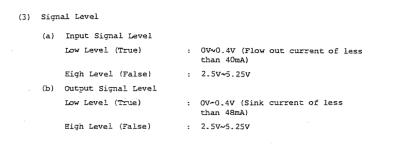
The drive datasheet also says:

1723303732197.png

Does that mean it requires 40mA of input current? And if that is so, the WD1770 would not be able to provide that much even for one drive...
 
Last edited:
What's the value of your termination resistor. The 74hc04 can only sink or source 4ma.
The 74ls06 can sink 40 ma., but source 0 ma.
 
What's the value of your termination resistor. The 74hc04 can only sink or source 4ma.
The 74ls06 can sink 40 ma., but source 0 ma.
Exactly - and this is the problem with using standard HC logic outputs in this application. Even the open-drain HC versions (like the 74HC07) will not be able to sink as much current as their LS versions (like the 74LS07). Sending a "logic 0" signal to two drives, along with the additional load of a pullup resistor provided by the terminator on one of the drives, located at the end of a long cable, might be beyond the ability of a standard HC output to reliably drive the signal to "logic 0". Likely if you use an 74LS open collector driver instead of the 74HC04 you are currently using, your problems will go away.
Incidentally the outputs of the floppy drives are open collector, and require a pullup resistor at the point each of these input signals are fed into your controller circuitry.
 
Last edited:
Exactly - and this is the problem with using standard HC logic outputs in this application. Even the open-drain HC versions (like the 74HC07) will not be able to sink as much current as their LS versions (like the 74LS07). Sending a "logic 0" signal to two drives, along with the additional load of a pullup resistor provided by the terminator on one of the drives, located at the end of a long cable, might be beyond the ability of a standard HC output to reliably drive the signal to "logic 0". Likely if you use an 74LS open collector driver instead of the 74HC04 you are currently using, your problems will go away.
Incidentally the outputs of the floppy drives are open collector, and require a pullup resistor at the point each of these input signals are fed into your controller circuitry.
Yours and jiang's replies are very insightful. I think I agree this must be the issue. I am waiting on a few 74LS06 buffers to see how it will work.

But at the moment I don't see anything else wrong with the circuit apart from this.

Incidentally, I did an experiment where I only use one of the drives, with the terminator removed, and everything works. This is strange as the terminators are needed. But I think it's just because of transients?

If I add the terminator with just 1 drive connected it won't work. Neither does it work with both connected and the end terminated. I think because of the sink issue.

What is weird is that it works with the terminator removed. Perhaps without a terminator, the driver input lines somehow float to around 5V by themselves by way of transients of something? I dont know why it should work without the terminators. I only tested seeking and stepping commands though, so the rest might not work.
 
Back
Top