• Please review our updated Terms and Rules here

RK8-E debugging

thunter0512

Veteran Member
Joined
Sep 27, 2020
Messages
1,027
Location
Perth in Western Australia
Recently I got a second RK8-E board set (M7104/M7105/M7106). Unfortunately all 3 boards have faults.
Multi-board subsystems are more difficult to debug, but fortunately @Roland Huisman has created H851 extenders which make debug-life much easier:

https://github.com/Roland-Huisman/Digital_PDP8_debug_tool_for_H851_connections

Thank you Roland!

I have built 8 of these and with 4 IDC cables of 30 cm length and a quad extender board I have a realistic chance of debugging and fixing this controller.

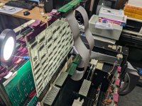
Here are some photos of my initial debug setup (click on the photo to see full size):
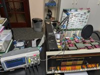
PXL_20240915_141643463.jpg

PXL_20240915_141700255.jpg

I am using the "DHRKA RK8E Diskless Control Test" maindec-08-dhrka-e-pb to trigger the faults and attempt to capture the relevant context via the attached oscilloscope.

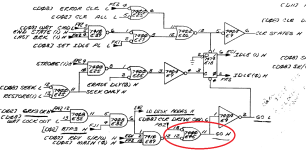
The first problem I see is that DRST ("Read Status") IOT reads an invalid status with the "Control Busy" bit spuriously set. The DRST part of the logic is implemented on the M7104 board.

It turns out that the DRST IOT correctly reports what it sees. The problem is that the controller is not in the IDLE state as indicated by the active low IDLE input being always high.

Here are the relevant parts of the schematic with the interesting parts highlighted (click to see full size):
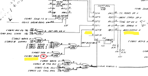
Spurious_busy_D03.png

Of course the IDLE bit is implemented on another board, the M7106. This means rearranging my debug setup.
I already have a suspect without even probing the board. The most likely candidate is the IDLE flipflop E18 a 7474 which seems to have a high failure rate.
 
I get to debug my RK8E soon so I am very interested in your experiences. I need to get a set of those top block extenders as I don't relish tacking wires to the points needing monitoring.

Thanks for posting!
 
As it turned out the problem was not the actual IDLE flipflop E18, but instead E45 a 7400 (quad NAND) where output 11 (signal "GO H") was in an invalid TTL state of 1.8V rather than the expected TTL low of 0V - 0.8V. This caused the PRESET input of the 7474 flipflop E18 to be always asserted (low) even when the RESET input was asserted (low) - this is bad and causes instability in the flipflop (RESET and PRESET asserted at the same time is a big NONO). I checked the only other part which loads the signal "GO H" - E19 another 7474 but it seemed fine.

I have replaced E45 and now the diagnostic runs noticeably longer before I halts with a new fault.
Oh well - one down a few (many?) more to go.

Here is the relevant part of the schematic not showing E19 which was fine (click on the images to see full size):

Spurious_busy_7400_faulty.png


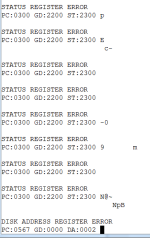
Here is a log of the terminal session (note the new error):

Spurious_busy_terminal_session.png

The garbage characters are from powering off the PDP-8/e.
 
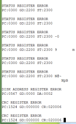
Hmmm - I run the diagnostic again and this time it run for a long time and then finally reported a "CRC Register Error" rather than the earlier "Disk Address Register Error".
I don't like faults which disappear by themselves. They are bound to come back.

Here is the latest terminal log:

Disk_address_and_CRC_errors.png
 
Debugging the RK8E controller has always been somewhat of a challenge. The numerous RK8E ECO's show this was the case even for DEC engineers. You might find RK8E controller board revisions of interest. Also check pp. 313-315 of PDP-8E_ECO_LOG_Dec74 for details on M7104, M7105, M7106 ECO's.
I think someone decided an updated design (RK8L) would be more cost-effective than installing ECOs. If anyone has a schematic for the RK8L M8371 module, please share it.
 
Last edited:
I think someone decided an updated design (RK8L) would be more cost-effective than installing ECOs. If anyone has a schematic for the RK8L M8371 module, please share it.
The Doug Jones University of Iowa Omnibus Module page says: Two board set replaces RK8E on PDP-8/A systems (never released? several survive)
 
Two board set replaces RK8E on PDP-8/A systems (never released? several survive)
We have the RK8L M8372 schematic. There's nothing about it that suggests it's 8/A specific. The RK8L is two quad Omnibus modules with two H851 over-the-top connectors. It'd work fine with the KK8E CPU. It might be possible to re-create the RK8L board set if we could ever locate a schematic for the M8371 (I/O Data Break Control) module.
 
We have the RK8L M8372 schematic. There's nothing about it that suggests it's 8/A specific. The RK8L is two quad Omnibus modules with two H851 over-the-top connectors. It'd work fine with the KK8E CPU. It might be possible to re-create the RK8L board set if we could ever locate a schematic for the M8371 (I/O Data Break Control) module.
Rather than recreating the DEC controllers directly I would clone the Plessey clone as IIRC it uses standard 74xx series TTL parts rather than unobtainable or super-expensive Signetics and Fairchild exotics.
The RK8L is using bipolar PROMs with undocumented content. This is a show stopper unless you have a working board set to extract the PROM contents from.

@Roland Huisman has made some nice 8/e clone boards using standard 74xx parts so it is possible to transform DEC weirdness into a design using currently available parts although in same cases you have to be a bit creative.
Nevertheless cloning the Plessey board should be easier.
 
Last edited:
Rather than recreating the DEC controllers directly I would clone the Plessey clone as IIRC it uses standard 74xx series TTL parts rather than unobtainable or super-expensive Signetics and Fairchild exotics.
The RK8L is using bipolar PROMs with undocumented content. This is a show stopper unless you have a working board set to extract the PROM contents from.

@Roland Huisman has made some nice 8/e clone boards using standard 74xx parts so it is possible to transform DEC weirdness into a design using currently available parts although in same cases you have to be a bit creative.
Nevertheless cloning the Plessey board should be easier.
I have 2 Plessey controller sets. One fails the diskless test, the other passes the diskless test but fails the read/write test.

I would be happy to lend a set to someone who wants to clone it. To look at signals or whatever.
 
Multi-board subsystems are more difficult to debug, but fortunately @Roland Huisman has created H851 extenders which make debug-life much easier:

https://github.com/Roland-Huisman/Digital_PDP8_debug_tool_for_H851_connections

Thank you Roland!

I have built 8 of these and with 4 IDC cables of 30 cm length and a quad extender board I have a realistic chance of debugging and fixing this controller.
I would like to build a set of those to help me debug my PDP-8/M. Can anybody suggest a source for suitable card edge connectors?
 
Today I spent a few hours looking at the "Disk Address Register Error".
The problem may be caused by the sector address stored in E96 a 7496 (on board M7106) but I have to confirm this when I am less tired.
 
Tom Goodman is selling them cheaper than I can buy them directly from the manufacturer.

If someone orders more over the top extender boards please let me know I would like in on the buy.

Thanks...
 
It's only $0.50 per board at quantity 10 before shipping, and I'm also going to be building another board at the same time which wants hard gold electroplated edge fingers. I've read that JLC can be cheaper than PCBway, but if I'm not mistaken, they don't offer hard gold electroplating and beveled edges; just ENIG, which isn't great for card edge fingers. So I'll be ordering from PCBway anyway, and the base cost of the electroplated card edge will swamp the higher DHL shipping cost from PCBway vs. JLC.

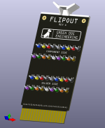
Y'all might like to see the other board I'm working on. It's still a work in progress, and it may be a while before I fabricate the first batch because of other life expenses which are inconveniently intruding upon my hobby finances. I call it "Flipout". It's a breakout board for general use probing the various DEC Flip-Chip derived backplanes, and my first use for it (along with the over-the-top adapters) will be debugging my PDP-8/M. I figure I might as well fabricate a bunch of them, since the electroplated edge connectors add a few hundred bucks to the base cost of the order.

FlipOut.png

Incidentally, this is also the first public reveal of the logo I had made for the freelance consulting business I'm working on spinning up. I haven't made up my mind yet about whether I'll include it on the Flipout boards when I make them. Who can guess the inspiration for the text font in the logo? It's retrocomputing related, but not DEC. It would normally be green on black, but PCBway doesn't offer green silkscreen.
 
Back
Top