• Please review our updated Terms and Rules here

RK8-E debugging

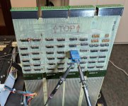
It's a breakout board for general use probing the various DEC Flip-Chip derived backplanes, and my first use for it (along with the over-the-top adapters) will be debugging my PDP-8/M.
In my experience, card extenders and DIP clips, along with the over-the-top extenders, are all you need to debug an Omnibus system. Directly probing the bus is generally not necessary. Perhaps adding test points to a quad height card extender would be more useful? You could also label the bus signals directly on the board that way.

Making some 3D printed DIP clips would be cool. I'd probably go in on a bunch of those, given how expensive the good ones are new and used.

I have thought about making a custom Omnibus extender with dual row headers for connecting a series of HP logic analyzer probes but haven't done so yet. It would be cool to generate an instruction trace to compare to SimH or the like.
 
My first thought was to make an Omnibus to logic analyzer breakout board to use with my big HP analyzer, too. But this is my first Omnibus system, and it’s not clear to me yet which signals have logic analyzer compatible voltages. So I decided to make a very generic test point board first to make it easier to explore the bus with an oscilloscope to see what is happening there.
 
Last edited:
Today I spent a few hours looking at the "Disk Address Register Error".
The problem may be caused by the sector address stored in E96 a 7496 (on board M7106) but I have to confirm this when I am less tired.

Today have been able to reliably reproduce the "Disk Address Register Error". It seems that this error only occurs once after power-up. Subsequent runs of the diagnostics do not fail with this specific error condition. Earlier I suspected that the sector & side storage in E96 is failing with bit 1 of the sector address being stuck high. I have now written two small self contained diagnostic programs which prove that the sector address and side is correctly stored and with the subsequent DMAN IOTs it is correctly clocked out on pin 10 of E96.

Here is the first which in a more comprehensible form replicates the maindec-08-dhrka-e-pb test starting at address 0547:

Code:
   1               / RK05 DIAGNOSTIC
   2                       DSKP=6741
   3                       DCLR=6742
   4                       DLAG=6743
   5                       DLCA=6744
   6                       DRST=6745
   7                       DLDC=6746
   8                       DMAN=6747
   9             
  10                       *20
  11 000020  0020  K0020,  0020
  12 000021  0200  K0200,  0200
  13 000022  1000  K1000,  1000
  14 000023  4000  K4000,  4000
  15             
  16                       *200
  17 000200  7301  START,  CLA CLL IAC     / AC = 1, LINK=0
  18 000201  6742          DCLR            / CLEAR AC AND CONTROLLER
  19 000202  7240          CLA CMA         / AC = 7777
  20 000203  6743          DLAG            / DISK ADDRESS REGISTER = 7777
  21 000204  7200          CLA             / AC = 0
  22 000205  6743          DLAG            / DISK ADDRESS REGISTER = 0000
  23             
  24 000206  7330          CLA CLL CML RAR / AC = 4000, LINK = 0
  25 000207  6747          DMAN            / ENTER MAINTENANCE MODE
  26 000210  7010          RAR             / AC = 2000
  27 000211  6747          DMAN            / ENABLE SHIFT TO DATA BUFFER RANK 4 (DB4)
  28 000212  7300          CLA CLL         / AC = 0000, LINK = 0
  29                     
  30 000213  1022          TAD K1000       / ENABLE SHIFT CRC
  31 000214  1021          TAD K0200       / ENABLE SHIFT SECTOR + SURFACE
  32 000215  6747          DMAN            / SHIFT SECTOR 5 TIMES
  33 000216  6747          DMAN            / 2                              
  34 000217  6747          DMAN            / 3                              
  35 000220  6747          DMAN            / 4                              
  36 000221  6747          DMAN            / 5                                      
  37                     
  38 000222  7300          CLA CLL
  39 000223  1022          TAD K1000       / ENABLE SHIFT CRC      
  40 000224  6747          DMAN            / SHIFT DA 7 TIMES
  41 000225  6747          DMAN            / 2                              
  42 000226  6747          DMAN            / 3                              
  43 000227  6747          DMAN            / 4                              
  44 000230  6747          DMAN            / 5                              
  45 000231  6747          DMAN            / 6                              
  46 000232  6747          DMAN            / 7                      
  47                     
  48 000233  7300          CLA CLL
  49 000234  1020          TAD K0020       / READ DATA BUFFER TO AC
  50 000235  6747          DMAN            / ..      
  51                     
  52 000236  7402  FINISH, HLT             / Normal good halt
  53 000237  5200          JMP START
  54                       $

After power-on the program above nicely reproduces the error just like maindec-08-dhrka-e-pb. With scope probes on E96 /CLR, CLK, D and QE I see the correct data being stored and subsequently shifted out on QE.

The following program is a refinement of the above where it loads 4 different data patterns into the disk address register and then clocks them out (only the 5 low order bits go into E96):

Code:
   1               / RK05 DIAGNOSTIC
   2                       DSKP=6741
   3                       DCLR=6742
   4                       DLAG=6743
   5                       DLCA=6744
   6                       DRST=6745
   7                       DLDC=6746
   8                       DMAN=6747
   9             
  10                       *20
  11 000020  0020  K0020,  0020
  12 000021  0200  K0200,  0200
  13 000022  1000  K1000,  1000
  14 000023  4000  K4000,  4000
  15 000024  5252  K5252,  5252
  16 000025  2525  K2525,  2525
  17             
  18                       *200
  19 000200  7301  START,  CLA CLL IAC     / AC = 1, LINK=0
  20 000201  6742          DCLR            / CLEAR AC AND CONTROLLER
  21 000202  7300  LOOP,   CLA CLL
  22 000203  1025          TAD K2525       / 2525
  23 000204  4215          JMS LDRD
  24 000205  7300          CLA CLL
  25 000206  1024          TAD K5252       / 5252
  26 000207  4215          JMS LDRD
  27 000210  7340          CLA CLL CMA     / 7777
  28 000211  4215          JMS LDRD      
  29 000212  7300          CLA CLL         / 0000
  30 000213  4215          JMS LDRD      
  31 000214  5202          JMP LOOP
  32             
  33 000215  7402  LDRD,   HLT
  34 000216  6743          DLAG            / DISK ADDRESS = AC
  35 000217  7330          CLA CLL CML RAR / AC = 4000, LINK = 0
  36 000220  6747          DMAN            / ENTER MAINTENANCE MODE
  37 000221  7010          RAR             / AC = 2000
  38 000222  6747          DMAN            / ENABLE SHIFT TO DATA BUFFER RANK 4 (DB4)
  39 000223  7300          CLA CLL         / AC = 0000, LINK = 0
  40                     
  41 000224  1022          TAD K1000       / ENABLE SHIFT CRC
  42 000225  1021          TAD K0200       / ENABLE SHIFT SECTOR + SURFACE
  43 000226  6747          DMAN            / SHIFT SECTOR 5 TIMES
  44 000227  6747          DMAN            / 2                              
  45 000230  6747          DMAN            / 3                              
  46 000231  6747          DMAN            / 4                              
  47 000232  6747          DMAN            / 5                                      
  48                     
  49 000233  7300          CLA CLL
  50 000234  1022          TAD K1000       / ENABLE SHIFT CRC      
  51 000235  6747          DMAN            / SHIFT DA 7 TIMES
  52 000236  6747          DMAN            / 2                              
  53 000237  6747          DMAN            / 3                              
  54 000240  6747          DMAN            / 4                              
  55 000241  6747          DMAN            / 5                              
  56 000242  6747          DMAN            / 6                              
  57 000243  6747          DMAN            / 7                      
  58                     
  59 000244  7300          CLA CLL
  60 000245  1020          TAD K0020       / READ DATA BUFFER TO AC
  61 000246  6747          DMAN            / ..      
  62                     
  63 000247  7402          HLT             / Normal good halt
  64 000250  7301          CLA CLL IAC     / AC = 1, LINK=0
  65 000251  6742          DCLR            / CLEAR AC AND CONTROLLER      
  66 000252  5615          JMP I LDRD
  67                       $

So all this means is that E96 is off the hook. The problem happens somewhere later where the data is shifted into Data Buffer Register 4. Unfortunately the data buffers are a very complex part of the circuit.

Earlier I have forced the diagnostics past the "Disk Address Register Error" and the "CRC Register Error" and found many problems all pointing to the Data Buffer Registers. So it may well be that a big chunk of errors disappear once I fixed the apparent problem in the Data Buffer Registers.
 
Last edited:
Today have been able to reliably reproduce the "Disk Address Register Error". It seems that this error only occurs once after power-up. Subsequent runs of the diagnostics do not fail with this specific error condition. Earlier I suspected that the sector & side storage in E96 is failing with bit 1 of the sector address being stuck high. I have now written two small self contained diagnostic programs which prove that the sector address and side is correctly stored and with the subsequent DMAN IOTs it is correctly clocked out on pin 10 of E96.

Here is the first which in a more comprehensible form replicates the maindec-08-dhrka-e-pb test starting at address 0547:

Code:
   1               / RK05 DIAGNOSTIC
   2                       DSKP=6741
   3                       DCLR=6742
   4                       DLAG=6743
   5                       DLCA=6744
   6                       DRST=6745
   7                       DLDC=6746
   8                       DMAN=6747
   9            
  10                       *20
  11 000020  0020  K0020,  0020
  12 000021  0200  K0200,  0200
  13 000022  1000  K1000,  1000
  14 000023  4000  K4000,  4000
  15            
  16                       *200
  17 000200  7301  START,  CLA CLL IAC     / AC = 1, LINK=0
  18 000201  6742          DCLR            / CLEAR AC AND CONTROLLER
  19 000202  7240          CLA CMA         / AC = 7777
  20 000203  6743          DLAG            / DISK ADDRESS REGISTER = 7777
  21 000204  7200          CLA             / AC = 0
  22 000205  6743          DLAG            / DISK ADDRESS REGISTER = 0000
  23            
  24 000206  7330          CLA CLL CML RAR / AC = 4000, LINK = 0
  25 000207  6747          DMAN            / ENTER MAINTENANCE MODE
  26 000210  7010          RAR             / AC = 2000
  27 000211  6747          DMAN            / ENABLE SHIFT TO DATA BUFFER RANK 4 (DB4)
  28 000212  7300          CLA CLL         / AC = 0000, LINK = 0
  29                    
  30 000213  1022          TAD K1000       / ENABLE SHIFT CRC
  31 000214  1021          TAD K0200       / ENABLE SHIFT SECTOR + SURFACE
  32 000215  6747          DMAN            / SHIFT SECTOR 5 TIMES
  33 000216  6747          DMAN            / 2                             
  34 000217  6747          DMAN            / 3                             
  35 000220  6747          DMAN            / 4                             
  36 000221  6747          DMAN            / 5                                     
  37                    
  38 000222  7300          CLA CLL
  39 000223  1022          TAD K1000       / ENABLE SHIFT CRC     
  40 000224  6747          DMAN            / SHIFT DA 7 TIMES
  41 000225  6747          DMAN            / 2                             
  42 000226  6747          DMAN            / 3                             
  43 000227  6747          DMAN            / 4                             
  44 000230  6747          DMAN            / 5                             
  45 000231  6747          DMAN            / 6                             
  46 000232  6747          DMAN            / 7                     
  47                    
  48 000233  7300          CLA CLL
  49 000234  1020          TAD K0020       / READ DATA BUFFER TO AC
  50 000235  6747          DMAN            / ..     
  51                    
  52 000236  7402  FINISH, HLT             / Normal good halt
  53 000237  5200          JMP START
  54                       $

After power-on the program above nicely reproduces the error just like maindec-08-dhrka-e-pb. With scope probes on E96 /CLR, CLK, D and QE I see the correct data being stored and subsequently shifted out on QE.

The following program is a refinement of the above where it loads 4 different data patterns into the disk address register and then clocks them out (only the 5 low order bits go into E96):

Code:
   1               / RK05 DIAGNOSTIC
   2                       DSKP=6741
   3                       DCLR=6742
   4                       DLAG=6743
   5                       DLCA=6744
   6                       DRST=6745
   7                       DLDC=6746
   8                       DMAN=6747
   9            
  10                       *20
  11 000020  0020  K0020,  0020
  12 000021  0200  K0200,  0200
  13 000022  1000  K1000,  1000
  14 000023  4000  K4000,  4000
  15 000024  5252  K5252,  5252
  16 000025  2525  K2525,  2525
  17            
  18                       *200
  19 000200  7301  START,  CLA CLL IAC     / AC = 1, LINK=0
  20 000201  6742          DCLR            / CLEAR AC AND CONTROLLER
  21 000202  7300  LOOP,   CLA CLL
  22 000203  1025          TAD K2525       / 2525
  23 000204  4215          JMS LDRD
  24 000205  7300          CLA CLL
  25 000206  1024          TAD K5252       / 5252
  26 000207  4215          JMS LDRD
  27 000210  7340          CLA CLL CMA     / 7777
  28 000211  4215          JMS LDRD     
  29 000212  7300          CLA CLL         / 0000
  30 000213  4215          JMS LDRD     
  31 000214  5202          JMP LOOP
  32            
  33 000215  7402  LDRD,   HLT
  34 000216  6743          DLAG            / DISK ADDRESS = AC
  35 000217  7330          CLA CLL CML RAR / AC = 4000, LINK = 0
  36 000220  6747          DMAN            / ENTER MAINTENANCE MODE
  37 000221  7010          RAR             / AC = 2000
  38 000222  6747          DMAN            / ENABLE SHIFT TO DATA BUFFER RANK 4 (DB4)
  39 000223  7300          CLA CLL         / AC = 0000, LINK = 0
  40                    
  41 000224  1022          TAD K1000       / ENABLE SHIFT CRC
  42 000225  1021          TAD K0200       / ENABLE SHIFT SECTOR + SURFACE
  43 000226  6747          DMAN            / SHIFT SECTOR 5 TIMES
  44 000227  6747          DMAN            / 2                             
  45 000230  6747          DMAN            / 3                             
  46 000231  6747          DMAN            / 4                             
  47 000232  6747          DMAN            / 5                                     
  48                    
  49 000233  7300          CLA CLL
  50 000234  1022          TAD K1000       / ENABLE SHIFT CRC     
  51 000235  6747          DMAN            / SHIFT DA 7 TIMES
  52 000236  6747          DMAN            / 2                             
  53 000237  6747          DMAN            / 3                             
  54 000240  6747          DMAN            / 4                             
  55 000241  6747          DMAN            / 5                             
  56 000242  6747          DMAN            / 6                             
  57 000243  6747          DMAN            / 7                     
  58                    
  59 000244  7300          CLA CLL
  60 000245  1020          TAD K0020       / READ DATA BUFFER TO AC
  61 000246  6747          DMAN            / ..     
  62                    
  63 000247  7402          HLT             / Normal good halt
  64 000250  7301          CLA CLL IAC     / AC = 1, LINK=0
  65 000251  6742          DCLR            / CLEAR AC AND CONTROLLER     
  66 000252  5615          JMP I LDRD
  67                       $

So all this means is that E96 is off the hook. The problem happens somewhere later where the data is shifted into Data Buffer Register 4. Unfortunately the data buffers are a very complex part of the circuit.

Earlier I have forced the diagnostics past the "Disk Address Register Error" and the "CRC Register Error" and found many problems all pointing to the Data Buffer Registers. So it may well be that a big chunk of errors disappear once I fixed the apparent problem in the Data Buffer Registers.

The Data Buffer Registers seems to be associated with the M7104. Have you been able to determine what ECO rev. your M7104 is at? What ECO rev. are your M7105 and M7106? Do any of the RK8E ECO problem symptoms seem to be related to what you're dealing with?
 
The Data Buffer Registers seems to be associated with the M7104. Have you been able to determine what ECO rev. your M7104 is at? What ECO rev. are your M7105 and M7106? Do any of the RK8E ECO problem symptoms seem to be related to what you're dealing with?
There are a lot of ECOs for the M7104. It seems that DEC engineers struggled to get this right.
The ECO text is not always sufficient to actually make the changes.
On page 8 of the PDP-8E_ECO_LOG_Dec74 under heading "FCO Kits" it refers to a "ECO Field Installation Order" which I suspect is the information needed to actually make the changes (plus the components).
Are the documents included in the "FCO Kits" available somewhere?
 
Last edited:
On my website are Eagle drawings for the M7104, Revision K schematic, as implemented on revision B of the PCB etch. The rework is drawn in yellow and green, as if done in inner layers instead of the actual wire-wrap wire that was used.

This may be useful to fill in some of the gaps in the ECO log.

Vince
Thanks Vince. I forgot about your Eagle schematics and PCB designs.
The schematics are much more readable than the originals.
I figured out how to turn off the top and bottom layers of the PCB in Eagle and it then nicely reveals the ECOs.
For anyone else interested, Vince's Eagle design of the M7104 is at: https://svn.so-much-stuff.com/svn/trunk/Eagle/projects/DEC/Mxxx/M7104/
For those of us without an Eagle license could you generate PDFs of the ECOs for future reference?
 
For those of us without an Eagle license could you generate PDFs of the ECOs for future reference?
I'm not sure how much better that would be than the existing photos:

It used to be the case that any newer Eagle could load the drawings, and the license only contstrained the editable area. I've only used versions up to V7, so I can only hope that is still true.
 
I also believe that KiCad's Eagle import should create something useable. (Though quite odd as KiCad drawings go.)

And a warning: the adds are easy to see; the cuts, not so much.
 
I also believe that KiCad's Eagle import should create something useable. (Though quite odd as KiCad drawings go.)
I loaded the M7104, M7105, and M7106 from so-much-stuff into EasyEDA to make it easier to trace RK8E signals. I believe the permissions of the imported files might be set to Public. Can check later when I’m on the computer.

Google Vince M7104 and it might show up
 
I have been doing more debugging of the spurious stuck bit 1 of the sector address.

It turns out that the problem appears to be caused by a stuck bit 1 of the CRC register instead.

The only reason that it shows up in the sector address is that the diagnostic shifts both CRC register and sector address register at the same time and the bits get ORed together. The expectation is that the 5 least significant bits of the CRC register are 0, so the ORing does not corrupt what is shifted into the Data Buffer DB4.

The maindec-08-dhrka-e-pb loads 0000 via DLAG into the DISK Adress Register which is really made up of the CRC register for the 7 bit cylinder address and the 5 bit sector address register, for the 1 bit side (or surface) and the 4 bit sector number. It then shifts 5 bits of the sector address register ORed with the 5 least significant bits of the CRC register into Data Buffer DB4. It then shifts the remaining 7 bits of cylinder address from the CRC register bits 11 - 5 into the upper 7 bits of DB4.

If I break this up into two separate shifts I can see the 7 least significant bits of the CRC register on the scope and clearly they have a value of 002. Of course this would not shift the correct cylinder address into DB4, but it proves that bit 1 of the CRC register is set.

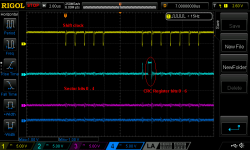
Here is a screen shot from the scope showing the first 5 bits of the sector address register and then the least significant 7 bits of the CRC register (note that the cylinder address "lives" in bits 11 - 5):

NewFile4_described.png

For the moment I am ignoring the bit 7 of the cylinder address which comes from the Command Register.
 
I have found the culprit causing all this trouble. It is E23 a 74174 (hex D-Type flip-flops with clear) on the Major Register board (M7105) drawing D04.

E23 implements bits 1, 2, 3 14, 15 and 16 of the CRC engine. CRC bit 15 (pin 12) is not clearing to low when the /CLR pin 1 toggles. All other bits become low.
During DMAIN shifting of the CRC register this is the second bit shifted out and is then ORed with the bit stream shifted from the sector address register causing the spurious sector address bit 1 being set.

In this text my bit numbering is the standard (sane) numbering with the least significant bit being 0. This is confusing with the DEC numbering where the most significant bit is 0. For my own sanity I use both in the (for me) appropriate context.

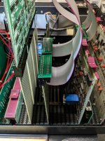
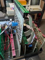
Here are some photos of the test setup with two boards being probed. The M7105 (Major Registers) is on an extender with two scope probes on the faulty E23. The M7104 which implements the Data Buffers is the last board. The M7105 which implements the Control is of no interest and is between M7105 and M7104. The 3 boards are connected with four H851 Debug cables.


PXL_20240920_153829246.jpg

PXL_20240920_153849442.jpg

PXL_20240920_153915689.jpg

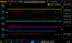
Here is the scope trace:

NewFile5_with_description_of_failure_to_clear.png

Note that the blue trace (E23 pin 12 - i.e. 5Q) remains high until it is shifted into bit CRC16 (E23 pin 15 - i.e 6Q). One clock pulse later it appears in the bitstream going to Data Buffer DB4.

It is midnight, so I won't swap the 74174 (E23) in this session. Tomorrow is another day. I have an LS and a F version of the IC in my parts stash, so I will put in a socket for now until I can find a plain 74174 (I have a few on order).
 
I have now replaced E23 on the Major Register board (M7105) drawing D04.
This has resolved the "Disk Address Register" error at location at maindec-08-dhrka-e-pb location 0567 as well as the "CRC Register Error" at location 1524.
When I now run maindec-08-dhrka-e-pb I get the following error:

DATA REGISTER ERROR
PC:1543 GD:7777 DB:0000
CR:000000 ST:2200 DB:0000 CM:0000 DA:0000

So far I have fixed the IDLE flag problem on the M7106 and just now the non-resetting CRC register bit problem on M7105.

The "Data Register Error" seems to points to the M7104 "Data Buffer & Status" board.

I know that all 3 boards were faulty, so it would not be surprising that M7104 is involved in this latest error.
 
Despite my initial hunch that the "Data Register Error" is caused by a problem on the M7104 "Data Buffer & Status" board, it turned out that the problem was on the M7106 "Control" board.

Rather than waiting for maindec-08-dhrka-e-pb to get to the problem I wrote the following small program based on what the diagnostic was doing:

Code:
   1               / RK05 DIAGNOSTIC
   2                       DSKP=6741
   3                       DCLR=6742
   4                       DLAG=6743
   5                       DLCA=6744
   6                       DRST=6745
   7                       DLDC=6746
   8                       DMAN=6747
   9              
  10                       *20
  11 000020  0002  K0002,  0002
  12 000021  0100  K0100,  0100
  13 000022  0020  K0020,  0020
  14              
  15               DECIMAL
  16 000023  7764  M12,    -12
  17              
  18               OCTAL
  19 000024  0000  BITCNT,  0
  20              
  21              
  22                       *200
  23 000200  7301  START,  CLA CLL IAC     / AC = 1, LINK=0
  24 000201  6742          DCLR            / CLEAR AC AND CONTROLLER
  25                      
  26 000202  7330          CLA CLL CML RAR / AC = 4000, LINK = 0
  27 000203  6747          DMAN            / ENTER MAINTENANCE MODE
  28              
  29 000204  7300          CLA CLL         / AC = 0000, LINK = 0      
  30 000205  1023          TAD M12
  31 000206  3024          DCA BITCNT
  32              
  33               LDDB1,                  / LOAD DATA BUFFER 1
  34 000207  7330          CLA CLL CML RAR / AC = 4000, LINK = 0
  35 000210  1021          TAD K0100       / SHIFT AC10 TO DB1
  36 000211  1020          TAD K0002       / SHIFT DATA BIT ONE
  37 000212  6747          DMAN            / DO IT
  38                      
  39 000213  2024          ISZ BITCNT
  40 000214  5207          JMP LDDB1
  41                      
  42 000215  7330          CLA CLL CML RAR / AC = 4000, LINK = 0
  43 000216  6747          DMAN            / ENTER MAINTENANCE MODE
  44                      
  45 000217  1022          TAD K0020       / TRANSFER DB4 TO AC
  46 000220  6747          DMAN            / ENTER MAINTENANCE MODE        
  47                            
  48 000221  7402  FINISH, HLT             / Normal good halt
  49 000222  5200          JMP START
  50                       $

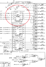
The "Data Buffer 1" logic relies on signal "12TH BIT OK H" coming via the H851 from the M7106 which implements the counters to detect 12th bit, 128th word and 256th word. The 12th bit counter was working fine, but the output was qualified by signal "INC CNTRS" (E12) and "INH 12TH BIT (1) H" (E13).

Here is the relevant part of the schematic with the faulty NAND gate circled in red:

E12 faulty.png

The output of E12 (7400 quad NAND gate) was stuck in TTL "no mans land". I didn't bother with a socket as I had the correct part and just swapped E12 for a new one. Subsequently the maindec-08-dhrka-e-pb run much longer and finally halted with the following error:

DATA BREAK ERROR
PC:3526 GD:0000 CM:4000 AD:0000 DT:0400

More fun tomorrow.
 
Last edited:
Today I investigated the cause of the "DATA BREAK ERROR" at PC:3526.

Again I wrote my own little diagnostic modeled on the relevant part of maindec-08-dhrka-e-pb:

Code:
   1               / RK05 DIAGNOSTIC
   2                       DSKP=6741
   3                       DCLR=6742
   4                       DLAG=6743
   5                       DLCA=6744
   6                       DRST=6745
   7                       DLDC=6746
   8                       DMAN=6747
   9              
  10                       *20
  11 000020  0020  K0020,  0020
  12 000021  0040  K0040,  0040
  13 000022  4000  K4000,  4000
  14              
  15               /EMA,    0070
  16 000023  0000  EMA,    0000
  17              
  18                       *1000
  19 001000  7301  START,  CLA CLL IAC     / AC = 1, LINK=0
  20 001001  6742          DCLR            / CLEAR AC AND CONTROLLER
  21                      
  22 001002  7330          CLA CLL CML RAR / AC = 4000, LINK = 0
  23 001003  6747          DMAN            / ENTER MAINTENANCE MODE
  24              
  25 001004  7300          CLA CLL         / LOAD CMD WRITE
  26 001005  1023          TAD EMA
  27 001006  1022          TAD K4000
  28 001007  6746          DLDC
  29              
  30 001010  7604          LAS             / GET DATA FROM SWITCH REGISTER AND STORE TO 0
  31 001011  3000          DCA 0
  32                      
  33 001012  7340          CLA CLL CMA     / LOAD CA WITH 7777 AND THEN 0000 (DLCA CLEAR AC)
  34 001013  6744          DLCA
  35 001014  6744          DLCA
  36                      
  37 001015  7300          CLA CLL         / MAINTENANCE BREAK TRANSFER
  38 001016  1021          TAD K0040
  39 001017  6747          DMAN
  40                      
  41 001020  7330          CLA CLL CML RAR / AC = 4000, LINK = 0
  42 001021  6747          DMAN            / ENTER MAINTENANCE MODE
  43                      
  44 001022  1020          TAD K0020       / TRANSFER DB4 TO AC
  45 001023  6747          DMAN            / ENTER MAINTENANCE MODE        
  46                            
  47 001024  7402  FINISH, HLT             / Normal good halt
  48 001025  5200          JMP START
  49                       $

This nicely allowed me to probe the specific failing bit 3 reported by maindec-08-dhrka-e-pb using switch register settings.

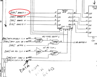
It turned out that when I attempted to do a DATA BREAK WRITE using maintenance mode bad data (BMD3 H - i.e. bit 3) was loaded into Data Buffer DB1 see sheet D01B:


E3 gets bad BMD3 H.png


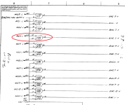
The source of the bad bit 3 was from a SP380 bus receiver on sheet D02B:

faulty E2.png


I had a bunch of DS8640 (from China) which are meant to be compatible with the SP380 and only a small number of SP380, so I replaced E2 with a socket and tried the Chinese DS8640 first. I did superficially tested a few of these when I got them and they seemed to work. Anyway after running my diagnostics with the Chinese rubbish I saw now bits 0 - 3 all stuck high. I am glad I used a socket.

After replacing the DS8640 with a SP380 my mini diagnostic was perfectly happy, but more importantly the maindec-08-dhrka-e-pb run a bit further:

OLD:
DATA BREAK ERROR
PC:3526 GD:0000 CM:4000 AD:0000 DT:0400
CR:007740 ST:2200 DB:0200 CM:4000 DA:0200

NEW:
DATA BREAK ERROR
PC:4034 GD:0000 CM:5000 AD:0000 DT:3774

So far I have replaced four ICs on the three board RK8-E set. Hopefully I am getting towards the end. :rolleyes:
 
I reproduced yesterday's "Data Break Error" at PC:4034 using the following program which is closely modeled on what maindec-08-dhrka-e-pb does, but on startup it sets all locations of Field 0 (except for the program itself) to the location's address. This quickly revealed that the top 4 bits of the Current Address register don't wrap from 0xF to 0x0. Instead it wraps from 7777 to 7000. I tried a few starting addresses including 1777 which wraps to 3000. This confirmed that the problem is in E8 a 74161 4-Bit Binary Counter which implements the topmost bits of the Current Address register.

Here is the program:

Code:
   1               / RK05 DIAGNOSTIC
   2                       DSKP=6741
   3                       DCLR=6742
   4                       DLAG=6743
   5                       DLCA=6744
   6                       DRST=6745
   7                       DLDC=6746
   8                       DMAN=6747
   9               
  10                       *0
  11               / FILL MEMORY LOCATIONS WITH ITS OWN ADDRESS
  12 000000  7300          CLA CLL
  13 000001  1074          TAD SADDR
  14 000002  3073          DCA CADDR
  15 000003  1073  LOOP,   TAD CADDR
  16 000004  3473          DCA I CADDR
  17 000005  2073          ISZ CADDR
  18 000006  5003          JMP LOOP
  19 000007  7402          HLT
  20               / EXERCISE CURRENT ADDRESS LOGIC       
  21 000010  7301  START,  CLA CLL IAC     / AC = 1, LINK=0
  22 000011  6742          DCLR            / CLEAR AC AND CONTROLLER
  23                       
  24 000012  7300          CLA CLL         / LOAD CA WITH 7776
  25 000013  1072          TAD K7776
  26 000014  6744          DLCA
  27                       
  28 000015  7330          CLA CLL CML RAR / AC = 4000, LINK = 0
  29 000016  6747          DMAN            / ENTER MAINTENANCE MODE
  30               
  31 000017  7300          CLA CLL         / LOAD CMD WRITE
  32 000020  1075          TAD EMA
  33 000021  1071          TAD K5000
  34 000022  6746          DLDC
  35                       
  36 000023  7300          CLA CLL         / 4 X MAINTENANCE BREAK TRANSFER
  37 000024  1067          TAD K0040
  38 000025  6747          DMAN       
  39 000026  7000          NOP
  40 000027  7000          NOP
  41                       
  42 000030  6747          DMAN
  43 000031  7000          NOP
  44 000032  7000          NOP
  45               
  46 000033  6747          DMAN
  47 000034  7000          NOP
  48 000035  7000          NOP       
  49               
  50 000036  6747          DMAN
  51 000037  7000          NOP
  52 000040  7000          NOP
  53               
  54 000041  7330          CLA CLL CML RAR / AC = 4000, LINK = 0
  55 000042  6747          DMAN            / ENTER MAINTENANCE MODE
  56 000043  1066          TAD K0020       / TRANSFER DB4 TO AC
  57 000044  6747          DMAN            / ...
  58 000045  7402          HLT             / EXAMINE FIRST WORD IN BUFFER
  59                       
  60 000046  7330          CLA CLL CML RAR / AC = 4000, LINK = 0
  61 000047  6747          DMAN            / ENTER MAINTENANCE MODE
  62 000050  1066          TAD K0020       / TRANSFER DB4 TO AC
  63 000051  6747          DMAN            / ...
  64 000052  7402          HLT             / EXAMINE SECOND WORD IN BUFFER
  65                               
  66 000053  7330          CLA CLL CML RAR / AC = 4000, LINK = 0
  67 000054  6747          DMAN            / ENTER MAINTENANCE MODE
  68 000055  1066          TAD K0020       / TRANSFER DB4 TO AC
  69 000056  6747          DMAN            / ...
  70 000057  7402          HLT             / EXAMINE SECOND WORD IN BUFFER
  71                                               
  72 000060  7330          CLA CLL CML RAR / AC = 4000, LINK = 0
  73 000061  6747          DMAN            / ENTER MAINTENANCE MODE
  74 000062  1066          TAD K0020       / TRANSFER DB4 TO AC
  75 000063  6747          DMAN            / ...
  76 000064  7402          HLT             / EXAMINE SECOND WORD IN BUFFER
  77                                                               
  78 000065  5010          JMP START
  79                       
  80 000066  0020  K0020,  0020
  81 000067  0040  K0040,  0040
  82 000070  4000  K4000,  4000
  83 000071  5000  K5000,  5000
  84 000072  7776  K7776,  7776
  85               
  86 000073  0000  CADDR,  0000       
  87 000074  0076  SADDR,  FILL       
  88 000075  0000  EMA,    0000
  89 000076  0000  FILL,   0000
  90                       $

And here is the relevant schematic with the faulty E8 highlighted by a red circle:

faulty E8.png

After replacing E8 the Diskless Control Test diagnostic maindec-08-dhrka-e-pb now passes:

OLD:
DATA BREAK ERROR
PC:4034 GD:0000 CM:5000 AD:0000 DT:3774

NEW:
RK8E DISKLESS PASS COMPLETE
 
Back
Top