Hello,
Trying to connect an SA801 to a standard 34 pin Shugart bus. (TRS-80 Model I). I’ve tried and it's just not working so hopefully someone can point out where I’ve gone wrong.
The SA801 was just checked, lubed, tested by a local company. I put it in a case with a new PS and connectors after it came back.
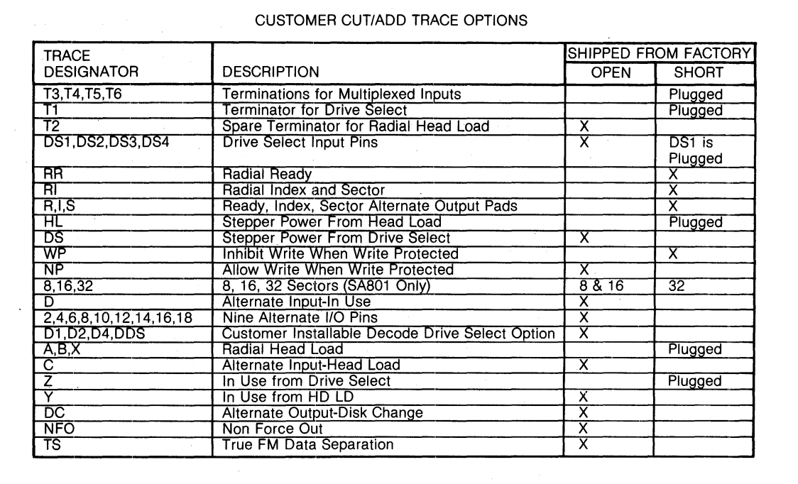
The jumpers on the SA801 when I got it back -
I closed all jumpers marked “Open” since I figured it was easier to control it externally than internally.
I bought 2 IDC’s, a 34 pin and a 50 pin. I connected all the 34 side grounds (1-33) to the same pin on the 50 side. I then jumpered 33 to 35, 35 to 37, etc until I got to 49, and I jumpered that to 1.
I then connected
32 is straight through since the TRS-80 needs Drive Select 3 to be on 32. (As opposed to 6)
My first issue is that if I plug this into an off computer, with drives at 0 and 2, with 34/2 to 50/2 for DCD, and 34/16 to 50/GND, 50/16 or 50/18 it starts spinning the motor on drive 2 (I can’t tell 0, it’s a virtual drive)
So 2nd problem is that if I just leave it with 34/16 unconnected, and try to boot the computer, it fails. If I remove the 50 pin connector, it fails to boot. If I remove the 34 pin connector, I can boot again.After it boots if I put the 34 pin connector back in, it still works. If I put the 50 back, it stops.
Any starts for debugging?
Thanks, Tuc
Trying to connect an SA801 to a standard 34 pin Shugart bus. (TRS-80 Model I). I’ve tried and it's just not working so hopefully someone can point out where I’ve gone wrong.
The SA801 was just checked, lubed, tested by a local company. I put it in a case with a new PS and connectors after it came back.
The jumpers on the SA801 when I got it back -
| Y/Z | Y |
| 800/801 | 800 |
| DS/HL | DS |
| T1 | Jumpered |
| A | Jumpered |
| B | Jumpered |
| X | Jumpered |
| DC/Pin 12 | Open |
| D/Pin 16 | Open |
| C/Pin 18 | Open |
| I/Pin 20 | No jumper, pads |
| R/Pin 22 | Open |
| S/Pin 24 | Pad |
| DS1/26 | Jumpered |
| T2 (After DS1) | Jumpered |
| DS2/28 | Open |
| DS3/30 | Open |
| DS4/32 | Open |
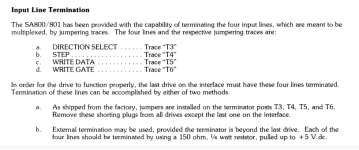
| T3/34 | Jumpered |
| T4/36 | Jumpered |
| T5/38 | Jumpered |
| T6/40 | Jumpered |
| RR | Jumpered |
I closed all jumpers marked “Open” since I figured it was easier to control it externally than internally.
I bought 2 IDC’s, a 34 pin and a 50 pin. I connected all the 34 side grounds (1-33) to the same pin on the 50 side. I then jumpered 33 to 35, 35 to 37, etc until I got to 49, and I jumpered that to 1.
I then connected
| 34 pin | 34 Signal Name | 50 pin |
| 2 | /DCD | 2 or GND depends, tried both |
| 4 | INUSE | X |
| 6 | /DS3 | X |
| 8 | /INDEX | 20 |
| 10 | /DS0 | 26 |
| 12 | /DS1 | 28 |
| 14 | /DS2 | 30 |
| 16 | /MTRON | GND or (16 or 18) - Problem |
| 18 | /DIR | 34 |
| 20 | /STEP | 36 |
| 22 | /WDATA | 38 |
| 24 | /WGATE | 40 |
| 26 | /TRK00 | 42 |
| 28 | /WPT | 44 |
| 30 | /RDATA | 46 |
| 32 | /SIDE1 | 32 |
| 34 | /RDY | 22 |
32 is straight through since the TRS-80 needs Drive Select 3 to be on 32. (As opposed to 6)
My first issue is that if I plug this into an off computer, with drives at 0 and 2, with 34/2 to 50/2 for DCD, and 34/16 to 50/GND, 50/16 or 50/18 it starts spinning the motor on drive 2 (I can’t tell 0, it’s a virtual drive)
So 2nd problem is that if I just leave it with 34/16 unconnected, and try to boot the computer, it fails. If I remove the 50 pin connector, it fails to boot. If I remove the 34 pin connector, I can boot again.After it boots if I put the 34 pin connector back in, it still works. If I put the 50 back, it stops.
Any starts for debugging?
Thanks, Tuc
")
") )
)