• Please review our updated Terms and Rules here

Tandy 1400 (any varients with HDD) - Expansion Slots Please Help!

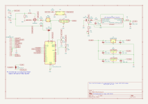
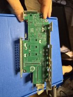
Thanks, pretty much just this. It's an adaptation of my XT-CF-Lite adapter, although actually it has more in common with my new small form-factor ISA IDE adapter. It should hopefully work with the LT, actually it's been drawn out from the LT service manual so probably more likley to work with that than the FD/HD :)

I know this is old, but I’m about to build your card. We’re you able to confirm that this works in a 1400LT?
 
Hello all,
C52 = 2200uF/25V
C43 = 1500uF/16V
C4, C14, C53 = 47uF/16V

R44 = 68k
R47 = 100k
 

Attachments

  • Tandy1400HD PSU.pdf
    302.7 KB · Views: 16
Well that is pretty awesome stuff @eightbitter, where did that schematic originate? Just curious...
...and by the way, thanks for posting the values as well!
 
Uhm... did @eightbitter just post the holy grail for 1400HD owners?!? I have maybe10-11 HDs and all but one have bad PSUs. AFAIK nearly all 1400HDs at this point have a failed or failing PSUs. I've had on my bucketlist for a long time to build and sell a low-cost PSU replacement PCB w/ a LiPo/LiFePO4 battery charger/recharging circuit. I'm selfishly motivated to get rid of most of my 1400HDs into loving forever-homes. But others would benefit too.

Also wrt to this thread, thanks to James for the expansion board for the 1400s. I have a couple myself and they work great in my LT/FDs!
 
Hey, schematic is my self-made and full of errors, I think, i.e. doubled R25 0.01 ohm.
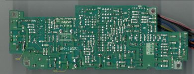
I have 2 Tandy 1400HD, both damages internal PSU. First, electrolytic capacitors need to be replaced, many are leaking in the converter circuits -12V, -24V, +12V.
 
Hey, schematic is my self-made and full of errors, I think, i.e. doubled R25 0.01 ohm.
I have 2 Tandy 1400HD, both damages internal PSU. First, electrolytic capacitors need to be replaced, many are leaking in the converter circuits -12V, -24V, +12V.
I just came into possession of a pair for 1400 machines, both with pretty much pristine everything but the internal PSUs. That Diagram will likely be enough to at least get me started on fixing or replacing them.
 
There are lots of errors, but it's a good start. I've started looking at it over the last few days. The signals you have labeled FDD and HDD are not for the disk drives. The HDD path is feeding the DC/AC boost converter for the electroluminescent backlight. The path labeled FDD is feeding the output of that ELBL high voltage AC back to the main board for sending to the LCD module. I plan on doing some additional testing with some of my 1400HDs this weekend.
 
Any idea how much current that -22v line needs? I’m eyeing some pre-built dc-dc converters (I’ve seen a few that produce a +/- output) but the negative side has very low output current. The -12 is almost certainly for RS-232, and https://forum.vcfed.org/index.php?threads/tandy-1400-hd-psu-bad-i-think.22317/post-920574 plus https://www.lo-tech.co.uk/wiki/Tandy_1400FD_PSUs seem to cover the pin out pretty well.

https://www.amazon.com/gp/product/B0CHRTY125/ref=ppx_yo_dt_b_asin_title_o00_s00?ie=UTF8&psc=1 look interesting, though it’s 24v not 22 and requires a load on the positive side.

I’m going to try a recap and fuse replacement first, but at least one of the psu’s is in really nasty shape. Worst case, I’ll probably have to cobble together two supplies… ugh
 
As to the diagram above: At least on the HD and FD models, that little daughter board wired between the yellow/black (j3) and green/black (j2) appears to be a switched 5v supply that might be controlled by the brown wire. I say might because I think I have a bad Q41 in this supply. I have two, one (I think) has a blown UPA1520H mosfet pack and blew both of it's fuses and the other mostly works after a recap. I had to replace every single Rubicon branded capacitor. They were all leaking nastily. Also, I think the White and Dark blue lines might be signal wires feeding to the main board rather than inputs to the PSU but I haven't fully traced them out.
 
I also made a diagram of the power supply daughter board, connected to the Yellow-Black and Green-Black wires. I'm attaching it.
 

Attachments

  • Daughter Board2.pdf
    107.5 KB · Views: 6
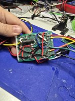
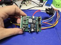
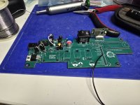
Well, I was able to get a 1400HD board that to start up and power the display with this monstrosity and this pinout


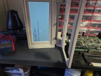
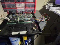
20240914_191245.jpg20240914_191242.jpg20240914_183303.jpg20240914_193843.jpg

Pins 1 (white), 2 (dark blue), 3 (brown) , 4 (Grey), and 5 (Light Blue) all appear to be some kind of single lines. The machine will come up without them but give you a low battery warning. You can probably get by without 6 (red +12v ) and 7 (purple -12v) but I waited until I had a +/- 12v module handy. I modified a +/- 24v module to give me -22v for pin 8 (orange -22v). This particular one needs a load of some kind on the positive side, so I put a 100k resistor just to have something there. Pins 9, 10, 11, and 12 are all ground. Pin 14 (green +5v) appears to be a switched 5v line and pin 15 (pink +5v) is always on 5v line. For this test, I just shorted them together. and yeah, this is a hand-wired nightmare of board using some cheap modules I purchased off amazon. From the side of the board with the zip tie to the right you a 2s charge circuit and an experimental isolation circuit I'm playing with that work let's you charge a 2s li-on battery in circuit, a 2amp variable voltage regulator I have set to 5v, at the top over board the modified +/- 22v module and at the bottom a +/- 12v module there's also a crude crowbar circuit in there that doesn't work right. I had to pull that part back out to get it functioning.

All that to say that you can get the mainboard and lcd to come up with only pins 6-15 and don't need the extra daughter board working to make it happen. I was actually surprised because I hadn't been able to get this board to actually bring up the lcd or backlight before. This is of course purely experimental right now, but it can run the machine off of the 2s battery or the stock 12v power supply. I'm planning to play around with the signal lines and a microcontroller to see if I can figure then out for certain. Might even try to make the switched 5v line work like it's supposed to (I think it supposed to put the machine in standby mode ...). I'll update the spread sheet as I figure those bits out. I'd do a board design but I'm not really that good with PSU design or layout work....
 
This has been very exciting to follow the collaboration as eightbitter's documentation and has fostered arlaneenalra's experimentation and yielded quite excellent results.
 
I currently have two of these. One is non-working, like most, but I have another one that I bought a couple of years ago, which was supposed to have had its power supply recapped, before I bought it and likely had, because it boots. The screen on that one has what looks like some minor lcd problems, but they are confined to a smallish area and haven't gotten worse comes up all the way to the hard drive, but you have to hold the power plug with some tension on it or else you entirely lose power.

Since this one boots, and in recent years, seemed to be the only one in existence that does, I've been way over-protective of it and have only started it a handful of times since I got it. As mentioned, it has an issue with the power plug that is a bit quirky and it has to be held, just right to boot, otherwise it just clicks a bit (engaging/disengaging a relay?) and I am hoping that it is finally the right time to attempt a repair with some of the additional information that has been posted recently.
 
I have four main boards one I bought as a bare board and three other I picked up in supposedly dead machines. So far, I've found a couple of the large caps on the main board leaked and power supplies that were almost trashed from leaking caps. The contrast and volume pots are also touchy. Other than that all of the main boards except one has actually come out ok after replacing those two caps (a 470uf 10v by the power lead and 1000~1200uf 10v over by the big transformer near the lcd connector). The one that failed seems to have a bad keyboard controller or something else wrong with that part of the system. Of the three machines that I've played with all of the backlights came back and the lcds work, though two of them have minor issues that seem to be causes by physical damage. Floppy drives seem to be iffy, I've got about 5 of them now between the machines. 2 work and the others I'm pretty sure have leaking caps that I haven't tracked down. A slightly modified gotek, to deal with the power pins that normally are ground lines, seems to work fine but you need one without an rotary encoder and can't leave even small form factor usd drives plugged in and close the lid. The one machine a I had with an hdd seems to have leaky caps on the hdd itself and I haven't dug into it yet to try to repair that. The xt-ide board for the 1400 will work, with the very late unit version of the xt-ide bios, but you can't use ctrl-alt-del with it last I checked.

All that to say the internal psu's are basically trash, but can be recapped if they haven't blown other parts (that's why I started looking into replacements). You may also have to readjust the voltages to the correct values, my boards don't seem to play nice with voltages below 5v and really need those two Rubicon caps on the board replaced. The mainboards themselves and lcds seems to pretty resilient based on the specimens I have. Personally, I'd pull your "dead" machines appart, check the fuses, and replace *all* of the electrolytic on the psu board, the little daughter card, and any that look suspect on the main board. So long as the volume trimmer and contrast know aren't damaged and the lcd is intact, it might just power up. You will want to clean up the cap juice and corrosion of course. Recapping took me about 2~3 hours cleaning as I went. In my case, the Rubicon caps were the bad ones, most of the other brands seemed to be fine.

Really need to write this up in a blog post ...
 
I've spent the last few weeks reverse engineering 1400HD power supplies and motherboards. I've made a few schematics that have allowed me to take a closer look at this design. I've made a schematic of the HDD MFM controller board. I've drawn the connections between the power supply and the motherboard (for example, the light blue wire is unused). I've attached a few of those schematics.
Problems with recognizing Alps HDD are caused by leaking capacitors on the controller board and the disk board. Long exposure to electrolyte on the boards ends with eating the tracks and damaging the electronics. On the 1400HD motherboard, a leaking capacitor at the large transformer next to the keyboard connectors caused the hc151 to have no contact with the board.

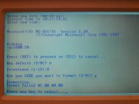
After cleaning up the HDD board and controller, the system recognized the disk, but formatting failed. After a thorough inspection, it turned out that the mylar tape connecting the disk board to the interior (platters) was damaged and was destroyed during the next disassembly. Interestingly, the disk formatted without contact with the heads, but after it was finished, it reported an error.

Another interesting thing is that trying to call the procedure (debug g=c800:5) caused the computer to hangup, while calling g=c800:50 or 45 or 30 worked correctly. Of course, interleave should be set to 3, not to 8, but this has no significance for the procedure itself.
 

Attachments

  • PSU2MB.pdf
    62 KB · Views: 4
  • HDD Controller.pdf
    85.1 KB · Views: 1
  • 1400HD PSU.jpg
    1400HD PSU.jpg
    760.7 KB · Views: 7
  • HD Formatting.jpg
    HD Formatting.jpg
    4.8 MB · Views: 7
Last edited:
Back
Top