• Please review our updated Terms and Rules here

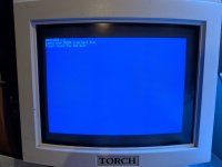
Torch Triple X c1985.

A small development. I measured the voltage again on the board and, with everything 'working' the 5v rail is sagging to 4.2v. The data sheet for the RTC (which has has the storage bytes for the keydisk number) says that the minimum operating voltage is 4.5v.... Hmmmmm. The RTC is definitely only getting 4.2v whereas the other (unused) molex connectors on the power supply have a slightly better, but still pretty terrible, 4.68v on the 5v rail. Of course, if I disconnect the motherboard then the power supply pumps out a healthy 5.09v.

At 4.2v I'm pretty surprised that anything is working at all although given the amount of old fashioned logic on the board I suppose it's probably not as sensitive as something like a Raspberry Pi to voltage drop.
 
I'd look into why it's sagging so much, most 74LS TTL is only specified to work correctly between 4.5 and 5.5 volts. Ideally it should be a bit tighter than that, but 4.2V is going to cause issues.

Is this the original Torch power supply?
 
I'd look into why it's sagging so much, most 74LS TTL is only specified to work correctly between 4.5 and 5.5 volts. Ideally it should be a bit tighter than that, but 4.2V is going to cause issues.

Is this the original Torch power supply?
No, it's a generic ATX supply. The original supply was effectively destroyed by the built in battery - I'm sure it was a good idea to include batteries in inaccessible locations at the time - and I did try to repair the circuit board. It did not go well... I repaired the damaged board, plugged it in but in series with an incandescent bulb and when I switched it on there were some fairly visible arcs across the board and the relay chattered and sparked before (I think) latching on. I switched it off as I didn't really feel happy poking my multimeter into it to see if the voltages were actually there. See here and here.

I still have the original board but while examining it after my escapades above I found a lot of components were severely damaged by the battery and basically fell off the board.
 
Good call not poking your multimeter into an active SMPSU, when I work on them it's always with a 12V-230V inverter so the power supply is "floating" relative to the mains. It's still a bit of a gamble, but it means you have to touch a ground path for any significant current to flow ... in theory, anyway.
Looking at the video, I'd call that fixable - it probably needs a good clean to get the last bits of electrolyte off, and the components around the battery replacing. Some of it's probably soaked into the board and is wreaking merry havoc, and if it's done that then I'd assume anything with corroded legs is probably compromised too.


Regarding the ATX power supply, where are the various power rails coming from, and going to? I guess you're using 5VSB for the Torch's backup battery/RTC supply?
I wonder if that's drawing too much power (ATX power supplies don't usually supply much on that rail) or it's fed through a diode somewhere and the Torch supply provides a higher voltage to compensate.
I'd be tempted to feed it with a dual-Schottky diode that sources it from 5VSB and one of the main 5V rails. When the power is off it'll use standby power, and when the Torch is running it'll use the meatier some-hundred-watts DC rail.
 
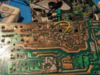
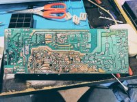
The damage to the underside of the board was pretty comprehensive..

PXL_20230917_192905596.jpgPXL_20230909_144500443~2.jpg
PXL_20230908_204931406.jpg

I still have all the parts (and schematic as mentioned) so it could probably be properly repairable given the time and inclination.. If I did manage to repair it then it would mean that the soft touch on/off would work and I'm sure I could figure out some way to get a battery installed but put somewhere in the case where it wouldn't cause issues in the event of a leak.
 
I'd say that looks worse than it is. I'd give it a clean with an ultrasonic cleaner, which should get all the electrolytic grot off. Then scrub the corrosion off the traces with a fibreglass pencil, repair the damaged tracks (I can see at least two in that second photo), and replace the damaged components.

The relay weirdness is probably down to tracking across the board from the battery electrolyte, a bad connection, or a combination of the two.
 
A couple of very minor things I tried. I 'borrowed' my son's PC power supply (rated at 500W) to drive the system and no change in behaviour. I had wondered if the voltage sag on the main board was because of the very 'used' nature of my power supply. I had had to replace some of the caps on it when I bought it. But a nearly new modern supply has the same behaviour.

I also swapped out the AM26LS31 chip with another known working one on the OMTI board. No change. There's the same trap message if the OMTI is set to SCSI ID 0 and no floppy activity if it's set to ID 1 or above.

I'm still wondering about the voltage at the RTC chip. Even though the system boots (as far as the key disk check), the RTC chip has only 4.5V and the 5V rail does not get above 4.6(ish) volts anywhere on the main board. Are there any ideas on what this might be and how I could track it down? 🤔
This is the point where I start suspecting RAM issues on the motherboard... If it's using DRAM, then a fault with DRAM refresh can cause a RAM test to pass, but the machine crashes out later.
The other thing I'd want to check is the data passing across the SCSI bus.

Regarding the RTC voltage, is the power supply feeding it measuring the full 5V?
The only things I can think that would cause a half-volt drop are a diode in the way, or your wires between the PSU and the RTC are too thin and you're getting voltage drop.
From hazy memory we figured that the RTC battery would also run the caretaker microprocessor (6805 wasn't it?) so this could account for a fair bit of current draw.
 
This is the point where I start suspecting RAM issues on the motherboard... If it's using DRAM, then a fault with DRAM refresh can cause a RAM test to pass, but the machine crashes out later.
The other thing I'd want to check is the data passing across the SCSI bus.
I did check all the RAM but it was a while ago and I have had at least two video RAM failures, so anything is possible.

I also tried using my 8-channel logic analyser on the SCSI bus but, to be fair, I don't really know what I'm looking at.. If I can dig out the plots I'll see if I can put them up on here (I used the Pulseview app - zip file found and attached).

Regarding the RTC voltage, is the power supply feeding it measuring the full 5V?
The only things I can think that would cause a half-volt drop are a diode in the way, or your wires between the PSU and the RTC are too thin and you're getting voltage drop.
From hazy memory we figured that the RTC battery would also run the caretaker microprocessor (6805 wasn't it?) so this could account for a fair bit of current draw.
Measuring the 5v rail at the main motherboard connector I get 4.6v. Without the motherboard the 5v rail from the supply is a rather more healthy 5.1v. The secondary processor is a 6303 and it seems happy enough with 4.6v. One thing I haven't done is see how much current is being drawn using my multimeter. Next time I'm in the shed I shall have a look at that. I will also check the cables and possibly beef them up a bit.
 

Attachments

  • logicplotstorchscsi.zip
    12.7 KB · Views: 1
I did check all the RAM but it was a while ago and I have had at least two video RAM failures, so anything is possible.

I also tried using my 8-channel logic analyser on the SCSI bus but, to be fair, I don't really know what I'm looking at.. If I can dig out the plots I'll see if I can put them up on here (I used the Pulseview app - zip file found and attached).
8 channels probably won't be enough - ideally you'd want the eight data bits, BSY, SEL, C/D, REQ and ACK.
If you can get a 16-channel logic analyser and connect it up to the SCSI connector, this protocol decoder should tell you what's going on with the bus: https://github.com/pcfx-devel/pcfx_scsi_sigrok_protocol_decoder

For each transfer you should get an Arbitration phase which is the Torch selecting the Omti (one would hope!), a Command phase which is the Torch asking the Omti to do something, and a Data phase which will be the data going in or out of the Omti.
For each byte of command or data, you'll see the transmitting device asserting REQ to indicate data is on the bus, the receiving device asserting ACQ when it has it, then REQ being deasserted.

Measuring the 5v rail at the main motherboard connector I get 4.6v. Without the motherboard the 5v rail from the supply is a rather more healthy 5.1v. The secondary processor is a 6303 and it seems happy enough with 4.6v. One thing I haven't done is see how much current is being drawn using my multimeter. Next time I'm in the shed I shall have a look at that. I will also check the cables and possibly beef them up a bit.
That sounds like you've got a fairly high current and the wiring isn't sufficient. A decent 500W PC power supply shouldn't sag by half a volt with only a relatively tame load.

For a 68000 workstation I'd want to be using 18 AWG as a minimum if there were more than one power and ground pin.
The Torch will likely have more than one 5V/GND pair which will all be tied together at the motherboard - this is to keep the resistance (and thus the voltage drop - V=IR) down. You need to wire as many of these 5V/GND pairs (ideally all of them) to a 5V/GND pair on the ATX connector.
 
So I tried the SCSI decoder but it doesn't work in Pulseview. It does work in DSView but my el cheapo logic analyser is ignored by it.

It's frustrating as I know I could get all the channels into one file on Pulseview by doing two runs through the boot (and including D0 in both as a marker) and then combining them. I actually have a combined file but it's in Pulseview.

I see three choices:

1) Get the el cheapo thing working with DSview - is this possible? I thought so as I've seen a Pi Pico as a logic analyser in use with DSview.
2) Figure out a way to convert my pulseview file into the DSview format
3) Try and re-work the SCSI decoder into a format that Pulesview is happy with
(option 4 would be to buy a 16 channel DS type logic analyser but that's way out of budget of £0.)
 
I can send you my 'saleae compatible' Chinesium 16ch analyser if it'll help the restoration effort. It works with the Logic software but you could probs also feed it into the sigrok protocol decoder Phil mentions.
 
Back
Top