Blast_Brothers
New Member
- Joined
- May 27, 2024
- Messages
- 4
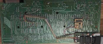
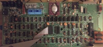
I acquired a broken Model 1 (Rev. G, lowercase, Level II, piggybacked 16K RAM chips with a daughterboard, so 32K?) years ago and am only just now getting around to fixing it. After replacing Z5, Z6, and Z57 I'm getting video out, but it just shows a screen full of garbage and I've been unable to narrow the problem down further. This is my first "big boy" repair so I'm hopeful that I'm just missing something obvious.
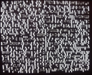
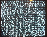
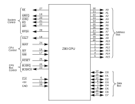
The pattern of garbage is almost, but not entirely, consistent between power cycles. In addition, sometimes there's a flickery black bar rolling down the screen, and sometimes there isn't. This is correlated with differences in CPU activity; when the bar is present, the address lines show activity, and when it's not, they're just stuck high or low. The CPU is getting a clock signal, and all of the input pins (INT, NMI, wait, BRQ, reset) are high as expected regardless of this (outside of some more noise on pin 24 when the bar is present) so I'm not sure where the inconsistency is coming from. I assume the black bar is the CPU interrupting the video display, but it's unable to initialize the machine for whatever reason?
The keyboard cable had disintegrated, so I replaced it with a detachable IDE cable. I'm measuring that some adjacent pins on the connector (12/13 on the keyboard side, and 15/16 and 18/19 on the mainboard side) are shorted together. Looking at the schematic I don't think that's supposed to be the case, so I'm assuming that some solder bridges formed under the IDE pin headers when I soldered them on? But that feels like something to look into after I get the rest of the unit working.
I've tried swapping the CPU, removing the CPU, unplugging the keyboard, and taking out the ROM and RAM shunts (and most combinations of these), and nothing changes the pattern of garbage, other than the black line never appearing when the CPU is out, which makes sense. I don't have any other spare parts on hand so I figured I'd ask for advice before ordering replacement RAM or ROM chips.