• Please review our updated Terms and Rules here

Undocumented, early SOL-20 PSU?

The Byte Attic

New Member
Joined
Aug 1, 2024
Messages
6
Hi all,
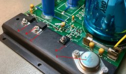
I've recently acquired a strange hybrid: a SOL-20 case, with PSU and keyboard, and a single-card computer in the S-100 expansion; no SOL motherboard. The PSU struck me as odd. Here's a photo after restoration (yes, I know the radial caps replacing the original axial ones look unauthentic, but this is a fully linearly-regulated PSU that produces ridiculous amounts of heat, so I chose 135C-rated capacitors for longevity, and they are only available in radial packaging):

IMG_2814.jpeg

As you can see, unlike the regular SOL-20 PSU, the transformer is mounted sideways, while the single bulk capacitor is mounted vertically. Also unlike the regular PSU, the 5V rail is linearly regulated with an LM323K:

IMG_2811.jpeg

I believe this was originally purchased as a kit, as the crowbar circuit was unpopulated (I populated it in the photo above) and the soldering job, although adequate, wasn't uniform.
Do any of you know the history of this particular revision? It is clearly an earlier iteration of the SOL-20 PSU we are all used to. Was this sold as a kit accompanying the SOL-10 perhaps? I can't find any documentation or references online. This isn't really a problem, as the circuit is extremely simple and easy to even guess from just looking at the components, let alone reverse engineer. But I just can't trace its place in the timeline.
I am posting it here in the hope of not only learning something from you, but also finding out if there is any historical significance to this beyond the SOL-20's own significance. This will go to a museum anyway, but if you guys know that this is a unique survivor, or something of that kind, I'd be happy to make all technical details available to the community. I, of course, kept all the original parts.
 
Last edited:
Did you take a photo before you worked on it ?

The thing is now it is hard to date it because at least two of the regulators look like they have been replaced (one TO-220 type has a thin tab) and the LM323 "steel" I don't think existed around the time of the sol-20
 
Last edited:
Also I have a picture attached.

I would not put this supply as it is back into my SOL-20...yet.

They made an interesting error in the supply design, they foolishly attached one of the regulators with a nylon screw. I have written about this problem on the forum before. The problem is as the regulator and the heat sink heats up the screw stretches and the force holding the regulator tab to the heat sink diminishes and the regulator overheats. It is also made worse if a modern sil-pad insulator is used under the device and not a mica washer, because the sil-pad type compresses slowly over time unlike Mica. They are good though if the device is held down by a constant force spring clip, rather than a screw

When mica washers are used they require thermal compound on both sides, it can be the modern white thermal paste, but clear silicone grease is fine.

A= thin tab regulator (didn't exist in the era of the sol 20)..no obvious thermal compound

B & C= likely sil-pad insulator and Nylon screw, needs to be replaced with 4-40 metal screw and round flange type insulating washer and ideally mica washer with compound on both sides and tightened up well.

D= No evidence of thermal compound or silicone grease on the mica washer on this device, recommend adding it.

E = modern replacement regulator, probably not original part.

You could also give consideration to adding thermal compound to this flange where it bolts to the SOL-20 chassis. It is a heat coupling flange really and not a heat-sink as such. It relies on being thermally coupled to the SOL's chassis to drag away the heat.
 

Attachments

  • SOL.jpg
    SOL.jpg
    274.7 KB · Views: 14
Last edited:
Also I have a picture attached.

I would not put this supply as it is back into my SOL-20...yet.

They made an interesting error in the supply design, they foolishly attached one of the regulators with a nylon screw. I have written about this problem on the forum before. The problem is as the regulator and the heat sink heats up the screw stretches and the force holding the regulator tab to the heat sink diminishes and the regulator overheats. It is also made worse if a modern sil-pad insulator is used under the device and not a mica washer, because the sil-pad type compresses slowly over time unlike Mica. They are good though if the device is held down by a constant force spring clip, rather than a screw

When mica washers are used they require thermal compound on both sides, it can be the modern white thermal paste, but clear silicone grease is fine.

A= thin tab regulator (didn't exist in the era of the sol 20)..no obvious thermal compound

B & C= likely sil-pad insulator and Nylon screw, needs to be replaced with 4-40 metal screw and round flange type insulating washer and ideally mica washer with compound on both sides and tightened up well.

D= No evidence of thermal compound or silicone grease on the mica washer on this device, recommend adding it.

E = modern replacement regulator, probably not original part.

You could also give consideration to adding thermal compound to this flange where it bolts to the SOL-20 chassis. It is a heat coupling flange really and not a heat-sink as such. It relies on being thermally coupled to the SOL's chassis to drag away the heat.Hi Hugo,

Hi Hugo,
Thanks for the feedback.
-- All three regulators have been swapped with brand new ones in the photos;
-- B: original nylon screw replaced with metal one, with nylon shoulder washer for insulation;
-- C: that is a mica insulator with grey thermal compound on both sides, in the photo;
-- D: this is the thyristor of the crowbar. It runs cold and only heats up when the crowbar closes, which will blow the fuse in a couple of seconds. Thermal compound is not critical here, only the mica insulator, as the thyristor's anode is the tab.
-- E: correct, the photo was taken after restoration. This is a modern LM323K with all the 'new' protections. There is thermal compound underneath it. You don't see it because I cleaned up the excess thoroughly.
-- The original did have an LM323K as well, which has been around for a very long time.
-- Yes, once the system is re-assembled the heat spreader will connect to the chassis with plenty of thermal compound.
Photo of the replaced parts, as per your request:

IMG_2826.JPG

This, however, won't tell you anything, as I believe this was a kit and could have been assembled, with new parts, at any point.
For clarity, I wasn't really looking for restoration advice -- though I appreciate the gesture -- but for historical information regarding this particular iteration of the SOL's PSU.
Cheers, Bernardo.
 
It is a good thing you got rid of those Tant capcitors, they will all short out sooner or later. Sometimes the older electrolyics can still be ok, but to test them reqiures, ESR, uF value and the leakage currents with full voltage applied. Sometimes old electros can look ok, but if the don't get tested for leakage current (on a power supply not with an Ohm meter) it is possible to miss ones that should be repalced.
Were the regulator devices and bridge rectifier actually faulty or did you replace them to be safe ?
 
It is a good thing you got rid of those Tant capcitors, they will all short out sooner or later. Sometimes the older electrolyics can still be ok, but to test them reqiures, ESR, uF value and the leakage currents with full voltage applied. Sometimes old electros can look ok, but if the don't get tested for leakage current (on a power supply not with an Ohm meter) it is possible to miss ones that should be repalced.
Were the regulator devices and bridge rectifier actually faulty or did you replace them to be safe ?Hi Hugo,

Hi Hugo,
I carefully measured all three electrolytic caps and changed the smaller ones because they were electrically leaking towards the top of their rated voltages. The large one was OK, with ESR below 1 Ohm, and I reformed it over three days. The regulators were changed preemptively; I did not test the originals.
Do you know anything about the history of this particular revision of the SOL-20? Here is a photo of the completed PSU.

1723459952351.jpeg
 
I have not seen that version before, but I think it would be a very late model version, because of the apprearance of the pcb. So maybe this is what the supply had evolved into, prior to the production of SOL 20's coming to an end.

Normally the large value capcxitors like the Mallory one there are not amenable to conventional testing.

The reason is that their uF values are so high, they exceed the values on many capcitance meters. On top of that, their ESR is so low that even when they are defective, their ESR is extremely low so that is no help either. As for the leakage current, if you multiply that by the terminal voltage, even if the dissipation was 1 Watt, you would not notice that either because of the massive physical size of the capcitor, it would not noticeably heat up.

There is only one way to check a cap like that properly, in circuit, and look at the ripple voltage and measure the current, you start with the formula for the capcitor Q= CV and differentiate it to dQ/dt = CdV/dt., or current I = CdV/dt

Then it is easy to see that the dV = Idt/C.

The time increment dt is 10mS in a 50Hz (full wave rectifier system) or around 8.3mS in a 60 Hz one. So you simply measure the ripple voltage on the capcitor's terminals in the computer, at some known supply current that you measure, and you can calculate the C vlaue supporting that ripple voltage, and compare that to the marked value on the capacitor, to find out if its uF value is about normal, or not. This is the only way I know of to check these large value capacitors.
Hi Hugo,
I've been doing this for a while, next to having academic education in the field and 28 years of professional experience. The PSU is working fine, near-zero ripple under load, as linear regulators deliver. All parts are properly tested and in spec.
What makes you think that this is a LATER, rather than an earlier PSU revision? The common one uses switch-mode regulation for the 5V rail, while this one uses a very expensive LM393. Is it the 78/79 date codes that motivate your suspicion? The parts could have been acquired later, but yes, the date codes seem to be consistent. Anyway, I'd appreciate further insights and details regarding the possibility that this is a later revision.
 
I'd have to look in my SOL again, away at the moment, I recall my pcb, it has the main filter cap off the board and the pcb does not have the green coating and is single sided looking more primitive and older looking, but it might only be by a couple of years probably made arounfd 1977. So when I say "later" only a little in the scheme of things. Most SOL's I have seen the capacitor is clamped to the chassis not on the pcb. My supply also matches the one in the manual.

However from the date codes your supply is clearly 1979 vintage or at latest early 1980, and I think was probably the final design they settled on in the SOL before the SOL went out of production.

I didn't know that the SOL had a switch-mode psu for the 5V ? The original supply, and the one in the manual uses a typical anaolg series pass regulator with a Darlington transistor arrangement, controlled by a pair of OP amps. One OP amp performs the current sensing & limiting, the other the voltage regulation and the circuit has an over-voltage SCR crowbar on its output . Maybe somebody mistook the design for an switching regulator.

Hi Hugo,
No, you are right, I misspoke. The 5V live indeed uses just a traditional pass-transistor arrangement and a Darlington pair. Mine uses the integrated LM393 instead.
Thanks for the further insights. Based on your feedback, I think I tend to agree with your assessment that this is a later, more consolidated version, eliminating one bulk cap and one bridge rectifier, and consolidating the 5V in an LM393. I can find no documentation for it, so I guess I'll have to document it myself. This unit will go to the Dutch Home Computer Museum (https://www.homecomputermuseum.nl/en/#intro) where it will be accessible to historians and future scholars, in the hope that this late chapter in the SOL-20's story can be reconstructed.
 
Back
Top