• Please review our updated Terms and Rules here

Teletype Model 43 schematic

Mike_Z

Veteran Member
Joined
Dec 1, 2013
Messages
1,713
Location
Near Milwaukee Wisconsin
Well, wouldn't you know it. I recently re inked the ribbon on my Model 43 printer and got it hooked up to my 8080 computer. Printed off a couple of programs and all of a sudden it stopped working AND there was a slight odor of smoke. My first thoughts were failed electrolytic capacitor. I pulled it apart and found that there is a 5, +12 and -12 volt regulators and there is a large electrolytic capacitor. With the power supply removed from the printer I also found a 1 amp fuse that was blown, it appears that this fuse is in the return of the 5, +12 and -12 volt supplies. I replaced the fuse and it held. I tried to measure the voltages on regulators, nut there was almost no voltage at all. The large capacitor has 180 volts on it so my attention was placed on the lower voltages. Carefully looking over the board I found a diode that looked heated, the fiberglass board underneath also showed heat damage. An in circuit test across this diode showed a short, I removed the diode and it appears OK, yet the diodes leads had that gun bluing look to them. With this diode out of the circuit I tried applying power again and the 5, +12 and -12 volt sources returned to normal. Apparently this diode is a supply for some other voltage. Seems that this diode feeds an unusual capacitor with 4 leads on it, can't figure that one out. I can try and trace the circuit out, but it would be a lot easier if I could find a schematic for this printer. I have the users manual, but that is of no help. Does anyone have these drawings or a place I can obtain a copy? I'd appreciate your help. Thanks, Mike
 
I don't have digital versions but I believe I have the complete set of sams here in an envelope thanks to another member here a few years ago.

Edited: Wow. Bitsavers doesn't even have these. Perhaps I should scan these in. PM me anyways.
 
I don't have digital versions but I believe I have the complete set of sams here in an envelope thanks to another member here a few years ago.

Edited: Wow. Bitsavers doesn't even have these. Perhaps I should scan these in. PM me anyways.

that would be a good thing. I've got a repair manual that I'll upload but I don't have any schematics
 
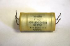
Well..... after poking around a little, there seems to be a common transformer for the 5, 12, -12 and this unknown voltage. Apparently when the unknow voltage was drawn down the other windings were incapable of supplying there loads. I found that the strange 4 wire capacitor seems to be shorted on all terminals. There is no manufactor name on this capacitor, It says it's a 530 uF-10+75% (value and tolerance) 50VDC, TYPE I 430705, + + 604D + +, 7826L (date code?), 2002. The 4 leads have me a little confused. Although on the circuit board two of the leads are tied together. The best I can figure is that this is a two for one capacitor. The odd thing is that the transformer winding that feeds this unknown voltage goes to a diode which connects to one lead of this 4 lead capacitor and no other place. I'm wondering if there is supposed to be an internal connection in this capacitor or is it a filter circuit. Any guesses?
IMG_0007.jpg
Thanks Mike
 
It appears that the numbers 604D are the important ones. A company Vishay/Sprauge make a 4 terminal capacitor, like the one I show in the picture above, but none of there datasheets show the internal connections. Mouser lists a replacement but it costs $120. I'm sure I can use two separate capacitors for much cheaper and get by. But I don't know how they should be connected, yet. Mike.
 
It appears that the numbers 604D are the important ones. A company Vishay/Sprauge make a 4 terminal capacitor, like the one I show in the picture above, but none of there datasheets show the internal connections. Mouser lists a replacement but it costs $120. I'm sure I can use two separate capacitors for much cheaper and get by. But I don't know how they should be connected, yet. Mike.

it is just 2 caps with a common + and -. They are tied together so it's just 1060uF. The supply is +42. two of the four holes on the board will be tied to ground, the other two are the output of the
rectifier and the other to the fuse, and 5.6k resistor.
I tried uploading the schematics, but it converted them to unreadable jpg thumbnails.
 
Gee, that seems odd, why in the world have two capacitors tied together internally and still provide 4 leads? Well,,, who knows. I'll try and see if that works a little later. I appreciate the help. I'd still be interested in any documentation you have, thanks. Mike
 
Hot Dog! This works, I replaced the failed capacitor with just one capacitor and the printer works again. Maybe I don't have the optimal connection, the reduced inductance etal, but Apparently I don't need it. Thanks to everyone who helped out. Also, if I can still get the schematics I'd appreciate it. Thanks a million, Mike.
 
Hot Dog! This works, I replaced the failed capacitor with just one capacitor and the printer works again. Maybe I don't have the optimal connection, the reduced inductance etal, but Apparently I don't need it. Thanks to everyone who helped out. Also, if I can still get the schematics I'd appreciate it. Thanks a million, Mike.

the manuals are on the mirrors now. the repair manual has the power supply schematic in it
http://www.mirrorservice.org/sites/www.bitsavers.org/pdf/teletype/43/
 
You know, I've had this printer for years and never had any trouble with it until now. For that matter, I've never had any documentation on it either. It's always been simple to use and reliable. Suppose I should clean it up and lube it some day. Thanks a lot for the information, it will help in the future, I appreciate it. Mike.
 
Hey, I know this thread is old, but I am restoring a Teletype Model 43 and have found several service manuals but no schematics. It sounds like they exist and would love to get them to help get things going. And the links here are broken. Thanks!
 
Last edited:
Back
Top