• Please review our updated Terms and Rules here

pdp 11/34 - a little help, please.

Hi All;

Robert, "" So, what would really help me today would be some advice on (a) any downsides to separating them like that and (b) whether it's safe to fire them up, briefly, before I do so. ""

I see no problem separating them, I would take lots of pictures, though, just in case you might want to put things back together at a later time..
On the Power supply, that is something that, needs more advice from those who actually have worked with these beasts.. But, having said that, here is what I can offer..
When trying especially for the first time or two 1. Do not put any boards in the machine, except maybe a terminator card, that way if something is wrong, especially if the voltage is too high, You won't blow up any boards that you cannot replace..
Measure All voltages.. I don't know if it will help or work with these kind of power supplies, but possibly a Dim Bulb Tester in line, might be a good idea as well..
Add a small board that is expendable, and remeasure the voltages..
I can't say about DEC Power Supplies, but on my old Varian, the Power Supply had drifted up from sitting around for too long and it put out 6.00 volts instead of 5.00 volts and that fried some things..
Let it run for awhile and re-measure.. Before adding anything of value to the mix.. And of course if any voltages are not within spec, don't go any further until it is fixed..

THANK YOU Marty
 
Are they H720 power supplies? If you tell me the model I can give you a couple things to check before you start. Also watch out being sometimes the wire and the plastic Molex connecters don’t age well and will crack and come apart.
 
Not sure. One has H775 on it, can't see anything on the others, but that doesn't mean it's not there - I just can't get to anything to look at it properly.

It's frustrating. I think I'd better separate them, get them on some shelves and recover some elbow room, before I get pissed off. Testing anything will have to wait.
 
Go ahead and pop it apart, would be the best way to clean. Generally what happens in the big DEC power supplies is that you have one huge transformer and DC supply that feeds two or three separate power regulator sections that take the high DC input and use a switching regulator to knock it down to the regulated voltage and all of that stuff can be separated, just take notes or pictures or something for when it goes back together. My experience has been that visual inspection will show things like leaky capacitors and overheated components. And it’s not unusual for the big filter capacitors to have died over time too. I don’t see any use to it myself but lots of people follow the idea that you can do capacitor reforming and this would be the time to do it. And remember that if you want to run the power supplies out of the system you will need some sort of load or they may not like it. I use old halogen headlights from cars to load down the 5 and 15 volt lines being there good for several amperes of load.
 
Oddly enough, a friend recently asked me if I'd ever reformed any caps. I replied that, if I had, it was surely by accident while bringing something up on a Variac.

OK, I have one of my three chassis separated (the second one in my earlier list). As I suspected, most of the weight is in the PSU - this one was an H765.

In case it helps anybody else, I removed the rails (I don't think you could do this in the rack - something would fall) and made sure that the top & bottom covers were off. There are three screws on each side - the top two are called "H765 Power System Screws" in the manual, the bottom two are called "Screw Hinge". Remove all six, stand the unit on one side (where a rail would go) and the two parts will separate.

There are four Molex connectors on the PSU to remove - P13 through 16, which are polarized and match up with J13 though 16, along with one ground wire. On the cage side, I had to cut a cable tie, then remove P1 from J1. The other Molex connector on the cage side is an unmarked 12 pin (9 used) job - it turned out to be polarized, but as I wasn't sure I drew a line with magic marker across both parts before separating them. In between, there's a flying connector - J2/P2. This runs from the PSU to the PSU, but separating it temporarily makes it easier to worm P1 out of the rest of the spaghetti.

I'll get these put up, then try another one.

Update: Two done now. I just separated the first one in my list, the actual pdp11/34. All was the same except that the ground from the cage went to a different point and there was an extra 2 wire connector to the center one of the middle three small Molex sockets (J3 and I have a drawing). Also, P1 was easier to remove, with no cable ties to cut. I'd forgotten how each unit of anything was slightly different in those days.

I had to take the lid off this one, to find a model #, but it's also a 765.

Second update: All three are now done. The last one also appears to be a 765, going by the part # of 70-13323-00.
 
Last edited:
Hoorah! I can now move about, once again and my truck is (mostly) empty.

The good thing about working for oneself is that you can goof off and mess about with a pdp11/34. The bad thing about working for oneself is that you do goof off and mess about with a pdp11/34. So, this will have to go on hold for a few days, while I do some actual profitable work, but I'll get back to it when I can.

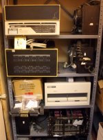
For now, here's a pic showing what I now think may be a pdp11/34a, two BA11 expansion chassis, three 765 psu assembles, the RX02 (with cable), the Ethernet adapter, all the rails and the box of cables (which includes a couple of the big white expansion chassis cables with Unibus cards on each end). Not pictured, are a couple of the pull out shelves, and other stuff like a funky chassis for delivering low voltage signals and all the cables that went to the funky opto I/O cards, etc). Now I can, at least, get to what I want, when I want it.

I'll do some reading and come back with questions and updates, as I have them, but if anybody is moved to offer any unsolicited hints, tips or comments, please have at it!

pdp1134.jpg
 
Yep! Good news and bad news! The good news is that your garage is starting to look like mine. The bad news is that your garage is starting to look like mine!

;-)
 
That’s got to be a heavy duty shelf to not be bowed from the weight on it! What condition were the Molex connectors in when they came apart? White or discolored yellow? Be careful when putting them back together because if they don’t lock tight they will tend to burn themselves up.
 
"Be careful when putting them back together because if they don’t lock tight they will tend to burn themselves up."

Even if the plastic shells lock up, even on brand new connectors, if the pins are free to move instead of mate fully with their opposite number, things could get more exciting than you want. I've had this happen on brand new gear. It doesn't get any better when the gear is 40~ years old.
 
I wish that was my garage. It's one tiny room of a 2000 sq ft building that I use as a workshop / warehouse and is the least cluttered area in it, the rest being wall to wall trip hazards. The shelving is medium duty - I have heavier.

The molex connectors were off white, but not full yellow and didn't seem terribly brittle. That's useful advice on making sure they make a good connection, thanks.
 
Well, I'm not doing as good a job of leaving this alone as I'd intended, but them's the breaks.

I've been trying to figure out what I have in the way of backplanes. The manual refers to a DD11-PK processor backplane (9 slot) and DD11-CK (4 slot) & DD11-DK (9 slot) expander backplanes.

However, the Unibus deals appear to be in blocks of four or eight slots and I have what looks like two 12 slot cages and one $largenumber (I'm typing this from home, so don't have them in front of me) slot cage, with the CPU in one of the 12 slot cages.

This suggests that I'm misunderstanding what the manual means by the word "slot". That seems like a rather fundamental error, so could somebody please put me straight before I continue further down the wrong path.
 
In looking at one of your previous posts, I see (in the CPU chassis) what appears to be a DD11-PK (9-slot) backplane and DD11-CK (4-slot) backplane connected together with an M920 jumper. Might that be what looks like a 12-slot backplane to you?
 
Yes, that sounds plausible. I probably shouldn't have posted this without going to my shop and counting the slots - I'm working off of memory and the same pics that you are.

I'm assuming that the wire wrap on each backplane is specific to it, so what I need to keep is the CPU chassis, with power supply and the necessary cards ( listed here ) along with the RX02.

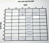
Before I do anything else, I guess I should make a drawing showing all of the slots and what's in each of them.

The rest of it, I should probably sell. I can see people buying backplanes, power supplies, card cages etc. but is anybody likely to want opto-isolated I/O cards and the like?

Edited to add: Apparently GE Canada is committed to running pdp11s until 2050, controlling robots in nuclear power plants. If they're using Unibus ones, there may be a market for those I/O cards after all!

http://www.theregister.co.uk/2013/06/19/nuke_plants_to_keep_pdp11_until_2050/
 
Last edited:
A "slot" will be the full-width of a plug-in module; in the case of a Unibus backplane - 6-wide, although some modules will be only 4-wde, 2-wide, or in really old modules 1-wide.*

[*Because of the traditional orientation orientation of DEC backplanes, this direction is referred to as "height" -- thus the terms hex-height and quad-height.]

A set of four slots is termed a "System Unit" (1 SU), and a chassis will be capacity-rated in SU (typically 5).

The mounting for a backplane consists of a metal frame and screw assemblies. This takes space. 1 SU includes this mounting space.

If one "merges" 2 SU into a single frame one recovers an extra slot, thus 9 slots become available - and it can hold 9 modules. The DD11-xx for SPCs (Small Peripheral Controllers) that you reference are thus 1 SU and 2 SU in size, but 4 and 9 slots/modules in capacity.

There are 3 SU backplanes (thus 14 slots/modules) but these are all specific to processors (CPU, cache, memory, a couple of SPCs) -- like the 11/60. There are even bigger ones backplanes (check out the 11/70!). The 11/34 backplane is just 2 SU (9 slots/modules).

Yes, backplanes are wired to very specific purposes. There is a metal tag or paper label on one of the long-edges that identifies the purpose. this can be hard to access/read when the SU is mounted :-<. Often there is information etched into the PCB that constitutes much of the backplane wiring; early backplanes did not use PCBs, but given the era of your equipment I doubt that you'll encounter any of these!
 
If one "merges" 2 SU into a single frame one recovers an extra slot, thus 9 slots become available - and it can hold 9 modules. The DD11-xx for SPCs (Small Peripheral Controllers) that you reference are thus 1 SU and 2 SU in size, but 4 and 9 slots/modules in capacity.

Thanks! That makes perfect sense and explains the apparent incongruity of an odd number of slots. I've printed out and scanned a page from the manual with drawings of the various backplanes. When I'm next in my workshop I'll blow the drawings up to full page size and use them to document exactly what is where, before doing anything else.

Presumably, somebody with wire-wrap skills and patience could rewire the first two slots of a DD11-DK, to turn it into a DD11-PK. Whether that would be worth doing would depend upon the availability of DD11-PKs, I guess.
 
Presumably, somebody with wire-wrap skills and patience could rewire the first two slots of a DD11-DK, to turn it into a DD11-PK. Whether that would be worth doing would depend upon the availability of DD11-PKs, I guess.

It's not quite that simple, particularly since the DD11-PK is definitely PCB-based (see: http://retrocmp.com/how-tos/setup-a-pdp-11-unibus-backplane). But that would be a way to approach the problem if you're backplane-less and want to set up an 11/34. An 11/04 (single-module CPU somewhat related to the 11/34) would be a better bet.
 
So, I've cataloged the first chassis and this might be a good point to stop and check a couple of assumptions.

1: I've assumed that, if you're standing in front of the cage and looking down at the cards, slot 1 is on the right and row A is at the back (based on the location of the CPU and the location of the grant cards).

2: Looking at the list of cards that I posted here for all three chassis, I note that there's only one M9302 far end terminator. That suggests to me that, as originally configured, there was a ribbon cable from the first chassis with the CPU to the third chassis in that post and then another from it to the second chassis, which has the terminator. I didn't record the location of the expansion ribbon cables, but I do have two of them.

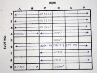
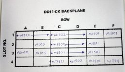
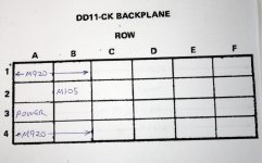
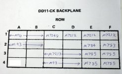
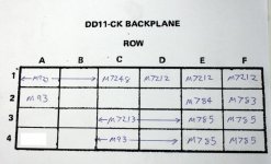
I'm attaching what I've drawn up so far. It seems that the DD11-PK has most of the computer, while the DD11-CK is mostly I/O cards (though I'm not sure about the M7821 Interrupt Controller) from its previous life as a DAQ system.

chassis1a.jpg

chassis1b.jpg
 
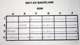
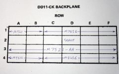
And here's the next one, what I called chassis # 2, above, but which I now believe was the last one in the chain. It has two DD11-CK expansion backplanes, that are pure wire wrap and one marked "DD11-C", which is a wire wrap / PCB hybrid. That last one has the FDD controller, the Ethernet adapter and the far end terminator, all of which I'll need for my system, along with a second RS232 card.

I'm not sure what to make of the huge void in the middle backplane. There's no grant cards, though they seem to be everywhere else they're needed, so I'm guessing that some cards were pulled prior to it being sold.

OK, just one more to go.

chassis2a.jpg

chassis2b.jpg

chassis2c.jpg
 
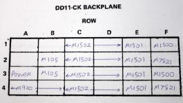
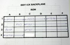
OK, last one. This has two DD11-CK expansion backplanes (pure wire wrap), followed by a DD11-DK (wire wrap / PCB) expansion backplane then a DD11-C hybrid backplane. There are two slots with nothing in row D, suggesting another couple of pulls, but I did notice two M93 bus terminators that I hadn't spotted previously.

Again, this seems to be mostly I/O, along with some repeaters. I'll leave thinking about those for later, I reckon.

I'm not sure how useful this part of the exercise was, but I feel better for having some drawings showing what's where, anyhow.

chassis3a.jpg
chassis3b.jpg
chassis3c.jpg
chassis3d.jpg
 

Attachments

  • chassis3d.jpg
    chassis3d.jpg
    80.6 KB · Views: 1
Last edited:
Hi All;

Robert, Could You keep this in mind, I don't expect You to know what You will need, nor want at the present..
But, as long as the price isn't too high.. Would You be willing to sell ONE of Your DD11-CK ?? I need a pure Wire-wrap unit..
A DD11-DK would be OK as long as it is pure Wire-wrap and the price isn't too high..
Please keep this in mind, I don't need an answer at present, Until after You have decided what You need for Your working System and what You can get rid of that are spares..
You are doing the right thing Identifying what You have and documenting things..
Keep up the good work.. Take Your time..

THANK YOU Marty
 
Back
Top