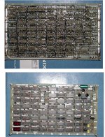
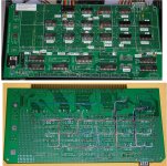
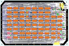
What do you mean "What thread am I in"? The one you just replied to me in. It's the "Kim-1 repairs continue thread". How could you not know, or am I missing something here? All I see above is a picture of the board connected to a Kim-1. I understand that people may not know about this or may want to make a PCB. Just thought that there are other Kim-1 people out there that might find this useful. Is that a problem? So I guess you mean in post #166? Since I don't have a Kim-1 I don't normally download something I have no use for. And that's much more than scroll up a few. 
Upcoming Events:
- VCF South West - June 14 - 16, Davidson-Gundy Alumni Center at University of Texas at Dallas
- VCF West - Aug 2 - 3, Computer History Museum, Mountain View, CA
- VCF Midwest - Sept 7 - 8 2024, Schaumburg, IL
- VCF SoCal - Mid February 2025, Location TBD, Southern CA
- VCF East - April 2025, Infoage Museum, Wall NJ
-
Please review our updated Terms and Rules here
You are using an out of date browser. It may not display this or other websites correctly.
You should upgrade or use an alternative browser.
You should upgrade or use an alternative browser.
KIM-1 Repairs continue
- Thread starter falter
- Start date
daver2
10k Member
>>> Cromemco (Z2-D, System 3)
Wasn't the BYTE shop by any chance was it?
Dave
Wasn't the BYTE shop by any chance was it?
Dave
circa77
Experienced Member
I'm going to reply despite sensing that explaining this to you may become exhausting. I did not reply to you, because I don't think you've been engaged in this conversation. I replied to those who have been actively involved in it over the past few days. The subject is KIM-1 repairs. Pictured is a KIM-1 board with a thing plugged into it. The discussion has been (in part) about a diagnostic board that someone other than me designed, but I just generated proper documentation for and an artisanally-wired copy of for myself, which is the previously-mentioned "thing" in the photo plugged into the KIM. Perhaps you'll be so kind, in the future, to catch up with what's going on before asking questions and making suggestions that make it very clear that you haven't bothered to catch up with what's going on.What do you mean "What thread am I in"? The one you just replied to me in. It's the "Kim-1 repairs continue thread". How could you not know, or am I missing something here? All I see above is a picture of the board connected to a Kim-1. I understand that people may not know about this or may want to make a PCB. Just thought that there are other Kim-1 people out there that might find this useful. Is that a problem? So I guess you mean in post #166? Since I don't have a Kim-1 I don't normally download something I have no use for. And that's much more than scroll up a few.
circa77
Experienced Member
No, The Computer Shop in Calgary, Canada.>>> Cromemco (Z2-D, System 3)
Wasn't the BYTE shop by any chance was it?
Dave
Of course I knew it was a KIM-1 repair thread. I know almost nothing about one as I have never had one or seen one. I merely asked specificallly what did your board do? Guess I should have passed on doing that. I won't make that mistake again with you.
circa77
Experienced Member
Thanks. I appreciate that.Of course I knew it was a KIM-1 repair thread. I know almost nothing about one as I have never had one or seen one. I merely asked specificallly what did your board do? Guess I should have passed on doing that. I won't make that mistake again with you.
[from subsequently-received PM:]
"I have put you on ignore as you're quite rude over my asking what your board did meaning actually what does it do to help debug the Kim. I know nothing about a Kim, not do I wish to from you."
Cool. So what you're saying is that you won't be barging into any more of our detailed and focused conversations again without first getting up to speed on them, then following up by calling me rude for pointing out what's not okay about what you just did. I think I can live with that.
Last edited:
Dwight Elvey
Veteran Member
Again, as he said, the entire thread was about fixing a KIM-1.
The board he made was from a design, for the diagnostic board, that I made a while back but lost the documents for ( erased the design files by accident ).
If you look back in the post you'll see that I'd made a number of kits to help fix theirs KIM-1's. The diagnostic board is used to do a series of simple minimal test
on one element of the KIM-1 at a time with the code in the EPROM. Along with the kits, I had parts to make a small replacement module to replace the 6530 chips.
If you look back far enough, you'll see my KIM-1 with the slightly raised 6532 chip ( similar to the RIOT 6530 ).
The original start of the thread was how to diagnose what had failed on the KIM-1. There is not a lot that will help. Debugging blind is extremely difficult because so
many individual pieces can fail and the result is the same, no LEDs displayed. The debug board does a series of test, selected by the dip switch.
Each test tries to be a test that uses a minimum of the KIM-1 at a time.
This is a little difficult because the 6502 normally uses the RAM ( a common failure point ) for most operations.
As an idea of how this works, the first testis to see if the CPU can execute instructions. This is a minimal test. The address decoder, the cpu chip and no buss
contention are need for this test.
The next test checks the RAM. To do a RAM test, you can't use the RAM so it needs to be done before latter test using the 6530s.
On like other diagnostics PROMs each test is selected by the switch that does single diagnostic test tries at a time with minimal support from the KIM-1.
This allows simpler diagnosing, with a scope or such.
I still assume some basic trouble shooting abilities. I can hold the scope probe for you.
The thread has evolved over time it started with me getting a broken KIM-1. It evolved in several early schematics for how one might make a simple diagnostic
EPROM to determine the problem.
A lot happened between then and now. While new people to the tread are always welcome. It does sometimes help to look at the beginning of the thread to see
where it has been and where it goes.
It is not a serious thing and sometimes people get touchy by post out of the blue. After all, it is an open forum. No foul so no harm done.
Dwight
Why would I care about kits specifically for a KIM-1? I enjoy reading the comments but since those don't apply to me I don't get into the details. I don't know why so many are so negative here? This used to be a positive forum. Seems like it's getting more and more like cctalk. Maybe it's time for me to drop this forum too. Ok, so he didn't care for my question. I got that. But to be so negative? Not everyone here is a pro on fixing older stuff. Actually I think I will drop this forum. Bye all.
circa77
Experienced Member
Silly person. Obviously I have no such problem with my west coast friend; the difference is whether someone is asking intelligent questions in a given context - or just leaping in without bothering to read first and expecting those he's intruding upon to do the work for him. Dwight, you exhibit the patience of a saint where I do not.
Dwight Elvey
Veteran Member
I've got side tracked with other things but it is really Dave that seems to have unlimited patience. I've worked with him on fixing a number of things. I get frustrated when I ask
for measurements and get answers like "it looks good". That is not a measurement! The other is getting scope pictures without voltage or sweep settings.
circa77 will try to make schematics of my tiny boards. He has more patience than I have and I designed them. While it is cool to try to make the tiny boards I show, they might be easier done on a board like Corsham's but using a little less real estate. I'll work with cica77 on this off line.
Dwight
circa77
Experienced Member
Well! Since you mention it (and you're the first RM65 guy I've run into in quite a while), I happen to have an original 8-slotHere are some examples: the Dazzler pcb's and for the 4 layer RM-65 video card and many more, including the Votrax Type 'N Talk:
www.worldphaco.com/uploads/THE%20RM65%20CRTC%20MODULE%20AND%20THE%20AIM.pdf
Rockwell card cage and backplane available - it's been sitting on ebay for a while with no takers, so I'm sure we could work
something out if you were interested. The card cage is very nice FRP instead of some metal business. I also just discovered
a stash of bare backplanes - 4 and 6 slot I think, though I'll have to confirm.
circa77
Experienced Member
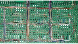
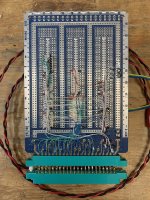
Since someone expressed surprise that someone would wire-wrap something like this, here's the bottom of the board.
I now refer to this as "artisanal wiring". It's sort of a joke. If I ever start referring to it as "bespoke wiring", though, anyone reading this is invited to pay me a visit at the earliest opportunity and slap some goddamn sense into me for sounding like a prat. I hate that word.
For the benefit of the kids who've never seen this: I've used Vector's Slit-n-Wrap my entire working life. It's fast to use because you don't have to cut and strip the wires, and reliable as all get-out. As you can see, I've always colour-coded my work: Red and black are (obviously) power supplies, green for address, white for control signals, and (usually) yellow for data. But I ran out of yellow and Digikey only has a monstrous spool in stock (rather than these little ones that perch atop the tool - see previous photo), so I went to blue, which is my "standby" colour. Just between us girls, the first time I used blue was when I was drinking with my mates and got a sudden inspiration for a circuit modification. I wasn't yet too drunk, though, to recognize that I'd better use a unique colour for the changes in case it turned out to be completely stupid. Worked okay that time, but blue's maintained that status since mainly as my "hammered work" colour.
Oh - and I'd never do this stuff without using Wrap IDs, those little plastic tags that push onto the wirewrap pins so you can keep the numbers straight.

Last edited:
Hugo Holden
Veteran Member
Since the topic of hand wiring has come up, I can say that I abandoned wire wrap many years ago. The reason was it drastically increases the profile of the board and the wire wrap pins are begging to get shorted out on any nearby conductor.
I'm glad I did, because if I had not, I would not have been able to make S-100 boards for my SOL-20, where there are few card slots and the boards closely stacked. A wire wrap board effectively uses two slots.
The system I use is to hand solder the connections, but the trick is routing the wires in groups and with pathways so that they do not cross over IC pins where connections need to be made as the build advances.
I have attached photos.
One is a Pong board I made back in 2003. It had about 900 to 1000 connections. It required very thin wire because of the number of conductors. Due to this they were less self supporting and required lacing into looms, I used some surgical silk thread to do it, if you look closely you can see it sitting on the tops of the many black wires. It was a helpful platform to iron out the six bugs of the original design before I hand designed the mini-pong pcb (which took 2 years on & off) image attached, many of the tracks on that board were more centrally located on the hand wired card.
When there are less conductors and the IC packing not as dense as Pong, I prefer to use heavier wires and to hold the conductors to the board. Another photo shows a light pen board and a close up photo of the technique and wire routing.
I also like lots of labels & test points, especially the ones with Gold plated loops for scope probes and multi-color glass beads.
Attachments
Last edited:
circa77
Experienced Member
Sure, it just depends on what the physical constraints you're under are.
There was also another non-ww system that used an IDC scheme - the board came fully-populated with socket pins with what looked like the blue Ansley "tulip" IDC pins on the underside, and you used a wiring pencil with a spool (much like the Slit-n-wrap tool), pushing the wire down into the pin and then going on to the next pin. I just can't recall the name at the moment - not Stitchwire, that was something else, but similar. I'm sure I have one of the boards in my lab, will try to spot it. Anyway, that eliminated the pin length "problem", which isn't a sound reason to abandon wire-wrap completely, as many situations don't demand a low-profile board - and also don't permit you to take two years to put one together.
One of the bigger ww designs I did was for a 68K-based controller for taking large seismic plots being done on a Geospace drum film plotter offline - the original controller throttled the host VAX 11/780 down to the plotter's actual drawing speed, which was rather wasteful of compute time. My controller replaced Geospace's Unibus board and buffered the plot, letting the VAX get back to more productive work. That was the first VAX Unibus design I did, and the first with PALs. I had a gas doing it, but sure didn't have years available for the job. Wire-wrap let me get it done in weeks.
Last edited:
Hugo Holden
Veteran Member
Actually the "two years" was to design the pcb track layout, not the hand wired board. I had the hand wired one done in a couple of months, just in my spare time after work.I'm sure I have one of the boards in my lab, will try to spot it. Anyway, that eliminated the pin length "problem", which isn't a sound reason to abandon wire-wrap completely, as many situations don't demand a low-profile board - and also don't permit you to take two years to put one together.
The 2 year one was the pcb track design, because it was not done with any auto-routing software. I created the design from scratch myself as "Artwork" as a .jpg image in a drawing program, drawing over a 2.54mm grid used as a transparency. It was all very old school. It took me a long while to be convinced that every track I routed could not have been done better.
Still, I have to agree there is something attractive about wire wrap too.
circa77
Experienced Member
I don't autoroute either - never have, probably never will - and I've done some fairly high-density SMT layouts. Your comment about having to convince yourself that every trace is the best possible, though, strikes uncomfortably close to home. On dense, serious, complex layouts (e.g. 200-pin .5mm lead pitch SMTs), a mildly-OCD personality can get into the work a little too deeply. After a month or so of 12-18-hour days in front of the screen I can find myself pushing traces around in my dreams, and ultimately (I recall this happening at the 6-8 week mark on a PCI design) there comes a point at which I have to catch myself and say "No, it's all routed, you're obsessing over trivial cosmetic 'improvements' that aren't going to affect this board's operation, and you have to stop now and tape out."
Then comes the shock of suddenly dropping off of a brutal, balls-to-the-wall work schedule, which is a completely different problem.
Anyway, I wasn't trying to get off into the weeds here - I am trying to keep it relevant to the KIM stuff. The point is that you can do some really complicated stuff with artisanal wiring, so you sure as hell don't need a PCB for small simple stuff, especially if you're only making one.
Last edited:
circa77
Experienced Member
Yeah, there it is. BICC-Vero Speedwire. I have one of the boards - an 8-bit ISA one - and always wanted to give the system a try, but by the time I got this board I was past doing ISA designs and into PCI work, so I never picked up the tool or wire. I'll have to dig out a catalog and see if I can find that stuff, because I still think it'd be fun to try it out. I don't know if they made S100 boards, but they did do DIN Eurocards, and I really love working in that form factor - been using it since the early 80s and it's still great. If you search Speedwire you can see pictures of the boards.There was also another non-ww system that used an IDC scheme - the board came fully-populated with socket pins with what looked like the blue Ansley "tulip" IDC pins on the underside, and you used a wiring pencil with a spool (much like the Slit-n-wrap tool), pushing the wire down into the pin and then going on to the next pin. I just can't recall the name at the moment - not Stitchwire, that was something else, but similar. I'm sure I have one of the boards in my lab, will try to spot it. Anyway, that eliminated the pin length "problem", which isn't a sound reason to abandon wire-wrap completely, as many situations don't demand a low-profile board - and also don't permit you to take two years to put one together.
circa77
Experienced Member
Really? Crickets? Tough room...Turn away from your CAD system and tape it like a man.
falter
Veteran Member
I did take a look at these while taking a break from the MMD-1, not exactly sure what I'm looking at. I was able to follow R/W from the cpu and see it inverted at U16b... connection is good..Back to the KIM-1...
It is possible to follow static signals (such as the read / not write signal) from the CPU through the interconnected logic gates to see whether the signals make sense.
This is possibly the end of the line unless we can think of something else...
The 1K of RAM (and the buffers) have to work. This RAM contains pages 0 and 1 of the 6502 memory, and this is important.
Likewise, the two ROMs in the 6530's are required.
I am just wondering if it is possible to attach an external EPROM to the bus expansion connector (along with a bit of address decoder logic) to test out basic functionality of the KIM devices. I think this is possible. Is this what the debug clip does I wonder. I will go and check...
Yep. This seems to be exactly what @Dwight Elvey's KIM-1 diagnostic card does, with a few bells and whistles! You need to beg, borrow or steal one of these cards...
Dave
I'll see if I can figure out how to build Dwight's diagnostic board if Dwight is good with that. Should be a fun little project. Personally I think $50 says the 6530-002 is the issue. Darn you Commodore.. why couldn't you just use normal ROM/EPROMs like everyone else.
Still kicking myself for selling off my other KIM-1. The first one I got - it was mounted in a nice case. I never even powered it up - this was before I understood how to do that. Sold it for $300 to pay for something else. I bet it worked.
daver2
10k Member
>>> I bet it worked.
Keep thinking it didn't and had the same faults as the MMD-1 and you will "push through the pain" !
!
Dave
Keep thinking it didn't and had the same faults as the MMD-1 and you will "push through the pain"
Dave

