• Please review our updated Terms and Rules here

KIM-1 Repairs continue

Err, no...

Did you disable DECEN and add the resistors to the data bus?

If so, the eight data lines should be DC VOLTAGES at where you set the pull-up resistors to...

Code:
DDDD DDDD
7654 3210
1110 1010 = $EA = NOP instruction.

Where a '1' should be +5V (> 4.5V) and a '0' should be 0V (< 0.5V).

Dave
 
Last edited:
Err, no...

Did you disable DECEN and add the resistors to the data bus?

If so, the eight data lines should be DC VOLTAGES at where you set the pull-up resistors to...

Code:
DDDD DDDD
7654 3210
1110 1010 = $EA = NOP instruction.

Where a '1' should be +5V (> 4.5V) and a '0' should be 0V (< 0.5V).

Dave
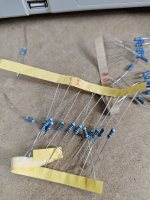
No haven't gotten that far, trying to find my 1k resistors. Yesterday I just took the opportunity to try and understand the scope a bit better, make sure I understood how to set it correctly and how to interpret what I'm reading for later. I have a million resistors I bought as a pack from ebay but they are all identical looking - the labelling on the paper that holds each grouping together is hard to read. Hopefully have that up and running in an hour or so if I can find the 1K
 
Nope.. these are not 1k.. they seem to be coming up as 90k. Wish they'd labeled and packaged these better. Back to hunting

20240104_112303.jpg
 
That accounts for the data bus readings then...

I bought a similar load of resistors years ago. I went through the whole lot one night with a digital meter and a bottle of wine and marked each up myself.

Years later (with worse eyesight to see the colour bands) I am very happy that I did!

Dave
 
Out about a thousand I've handled so far, I have found exactly *1* 1k resistor. Ugh.

These cheapo ones.. they get loose from their paper bindings easily, spill out all over the place. The stamping of resistance values is horrendous. But they were cheap I guess.
 
Yeah, I know the band code for them thankfully but.. yeah. I have a bad feeling I used these on another project, hence not in the drawer I keep them in.

If worst came to worst, could I chain two 500ohm together to get same thing? Or does that introduce problems?
 
How much does wattage matter? I have this parts board and it has several (I think) 1/4 watt 1k resistors like the one I found.. but also some larger ones which if I'm not mistaken handle higher wattage.. not sure exactly if these are 1/2 or 1w? Does that matter for our purposes?
 

Attachments

  • 20240104_123602.jpg
    20240104_123602.jpg
    1.9 MB · Views: 4
You can use 470 Ohm, 500 Ohm, 2.2k - these are only pull-up resistors. The value is largely immaterial..

The pull-down resistors to 0V/GND need to be fairly low - hence I specified about 100 Ohms - but something there or there about will do.

Dave
 
All done.

I'm starting to get the hang of this scope!

So I wired up everything as directed and verified the DECEN line had been pulled high via a 1k ohm resistor.

Next after hitting reset, I checked the data pins from D0 to D7, and verified each was 0V or 4ishV corresponding with the binary number we wanted, and that lined up. D0 was 0V, D1 was 4V or so (for some reason my scope doesn't show a decimal voltage number.. so I'm interpreting via 1V divisions onscreen, D2 was 0V, D3 was 4V, D4 was 0V, and then D5, D6 and D7 were 4V. So far so good.

Pin 7 SYNC showed a steady square wave.

Starting at A0 on the RAM, we had 250khz, A1 was 125khz, and in sequence the next pins were all 1/2 of the pin before it, I think the last one, A9, was .488hz.
 
It seems that the CPU is correctly executing NOPs then...

I will have a look tomorrow and post details of what else can be checked.

Dave
 
Many thanks for your time and apparently bottomless patience.

I might open up a third front tonight and try having a look again at that MMD1 now that I understand the scope controls more. Curious to see what the clock signal is doing, etc. I have 3 days before my wife and kids are back and must pack up at least two of these machines!
 
Just back from some errands in the city and lunch with an old pal - got a new pair of data acquistion boards for the Tektronix logic analyzer and a couple of NAS boxes - my network can use a few more TB of storage!

First, crank up the vertical, dude, to 11. Well, maybe not quite that high, but at least to 1V/div. Fill up the display so you can see stuff. You can always shorten the traces later to make space when you're probing two channels.

Resistors: If you stick with 5%, you'll rarely make mistakes reading the colour code. It's when you go down to 1% that you get an extra band and things can be confusing. And you don't need precision resistors for what you're doing!

Oh - and you know what another worthwhile exercise is? Working out, based on the resistance and a crude approximation of voltage (e.g. 5) how much power each of those resistors is dissipating. That'll tell you what wattage rating you need. It's just Ohm's law.
 
Last edited:
Oh - and you know what another worthwhile exercise is? Working out, based on the resistance and a crude approximation of voltage (e.g. 5) how much power each of those resistors is dissipating. That'll tell you what wattage rating you need. It's just Ohm's law.
For the benefit of the OP:

Ohm's law specified the relation between voltage V acros the resistor's terminals , current I and resistance R as V=IR. You have to algebraically juggle it to calculate power:

V = IR, multiply both sides by V:

V^2 =VIR VI = volts x amps = power, therefore V^2/R = Power in Watts.

The simplest version of the formula to remember is Power = V^2/R. where V is the voltage applied to the resistor.

So in a 5V system, with say a 1000 Ohm resistor the highest power dissipation you can get in the resistor with a constant 5v applied to it is (5x5)1000 = 0.025 watts, only 1/10 the power rating of the 1/4 watt resistor.

A 100 Ohm resistor would have 0.25W dissipated in it with 5V DC applied or 5V rms applied. And that is quite hot to the touch for a small object like a 1/4 watt resistor.

Physically larger resistors have a lower thermal resistance, a figure with proportions of degrees C per Watt, so they heat up less for the same applied power as a physically smaller resistor. Over the years resistors got smaller for the same max power rating, because the materials were more tolerant of higher temperatures.
 
For the benefit of the OP:

Ohm's law specified the relation between voltage V acros the resistor's terminals , current I and resistance R as V=IR. You have to algebraically juggle it to calculate power:

V = IR, multiply both sides by V:

V^2 =VIR VI = volts x amps = power, therefore V^2/R = Power in Watts.

The simplest version of the formula to remember is Power = V^2/R. where V is the voltage applied to the resistor.

Well, this was supposed to be an exercise for our friend to work out, not a lecture.

The math is even simpler if you go: V/R=I, so that'll give you the current through the part. Multiply that I by the V to get power in Watts.

So in a 5V system, with say a 1000 Ohm resistor the highest power dissipation you can get in the resistor with a constant 5v applied to it is (5x5)1000 = 0.025 watts, only 1/10 the power rating of the 1/4 watt resistor.

A 100 Ohm resistor would have 0.25W dissipated in it with 5V DC applied or 5V rms applied. And that is quite hot to the touch for a small object like a 1/4 watt resistor.

Except that that's the absolute maximum power dissipation if you clamp that resistor between the supply rails, but that's not what's happening here - these bus signals have a much lower duty cycle, so a 1/4W resistor isn't going to break a sweat, let alone burn a finger.
 
Well, this was supposed to be an exercise for our friend to work out, not a lecture.

The math is even simpler if you go: V/R=I, so that'll give you the current through the part. Multiply that I by the V to get power in Watts.


Except that that's the absolute maximum power dissipation if you clamp that resistor between the supply rails, but that's not what's happening here - these bus signals have a much lower duty cycle, so a 1/4W resistor isn't going to break a sweat, let alone burn a finger.
Yes as you point out, if the waveforms are pulses the power drops.

One interesting thing, if you have a pulsed DC waveform, with say a 50% duty cycle, like a square wave, you end up dissipating half the power.

This fact can be used to avoid doing the calculus when somebody asks the question :

What is the equivalent rms voltage, if you pass a sinewave, like the 115V AC line power via a rectifier, to say power a lamp with half wave AC ?

Since the power is halved, but power relates to the square of the voltage, and say if you consider the original power P1 and Voltage V1 and the power after half wave rectification P2 and the new rms voltage V2, and the fact that P2 = P1/2 then V1^2 = 2V2^2 , then V2 = V1 x 1/root2 = V1 x 0.707.

So if you half wave 115V line power through a rectifier, the equivalent rms voltage (heating voltage) is 0.707 x 115 = 80.5 volts (a poor man's light dimmer perhaps, the diode power losses are small). But it avoids the math, having to integrate the half wave rectified waveform over the 360 degrees of the cycle.

I prefer to avoid excessive math myself, but I still like to know how to do it.

I found it was possible to solve the resistor cube question, using virtually no math at all, if I invoked the notion of a Bandsaw cutting up metal plates. This can be atonement for the lecture you accused me of:

www.worldphaco.com/uploads/A_SELF_EVIDENT_SOLUTION_TO_THE_RESISTOR_CUBE_QUESTION_USING_THE_BANDSAW_METHOD.pdf
 
Well, my intent was certainly not to accuse you of lecturing, rather just to suggest that the concept be offered as an exercise for the reader rather than explained.

And if we're getting detailed, let's not forget that filament's nonlinear behaviour, so let's not get detailed.

Though I do like the bandsaw method... sheet resistance and topology together for the first time, like peanut butter and chocolate!

But we're getting a little OT...
 
Back to the KIM-1...

It is possible to follow static signals (such as the read / not write signal) from the CPU through the interconnected logic gates to see whether the signals make sense.

This is possibly the end of the line unless we can think of something else...

The 1K of RAM (and the buffers) have to work. This RAM contains pages 0 and 1 of the 6502 memory, and this is important.

Likewise, the two ROMs in the 6530's are required.

I am just wondering if it is possible to attach an external EPROM to the bus expansion connector (along with a bit of address decoder logic) to test out basic functionality of the KIM devices. I think this is possible. Is this what the debug clip does I wonder. I will go and check...

Yep. This seems to be exactly what @Dwight Elvey's KIM-1 diagnostic card does, with a few bells and whistles! You need to beg, borrow or steal one of these cards...

Dave
 
Last edited:
Back
Top