Hugo Holden
Veteran Member
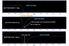
For momentary press ( less than ~1 seconds, /RESET and /DIAG go low and high in unison. So by the time the CPU has started looking for the /DIAG line, it is high and a normal RESET is performed.
View attachment 1258315
For a longer press, /DIAG is held low, and /RESET slowly ramps up to HIGH ( about 3.8v, though may be more or less depending ) over a matter of seconds. Once /RESET reached logic HI, the RESET operation starts while the button is still pressed and /DIAG is LOW.
View attachment 1258316
When the button is released, both go high, but as /RESET is already HI and /DIAG has been read, so it won't matter. This design does not require a bi-level switch, and only GND, /DIAG and /RESET. This should work if reset action actually occurs from a LOW --> HIGH transition. You can probabaly futz around with the value of the capacitor and resistor. "At least in the simulator" LOL It also assumes /RESET is the CPU's reset line which halts on logic low, and performs the reset transitioning back to HIGH.
That circuit won't work properly in the actual PET for two reasons:
One is there is no resistor to discharge the capacitor and turn the circuit to its original state prior to the next use of it (except for extremely low diode leakage). So it will only work once for a reset and that function will fail after its first use once the capacitor is charged. Also when the computer is line powered of, after that, re-powering it will take the side of the capacitor connected to the diode to -5V. Its easy enough in the simulator to set the capacitors initial voltage at 0, but you have to consider how it could get back to that state later.
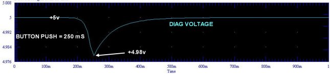
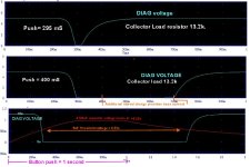
On my PET at least, the minimum resistance value on the DIAG line to pull it low enough, that it is interpreted as a logic low is close to 3.3k, for example a 4.7k won't do it, so modelling the source resistance for that at 100k won't work. This is one of the many reasons I used a transistor to drive the DIAG line, so it can sink enough current to get a solid logic low.
")