nikola-wan
Veteran Member
I made progress on my 4054A display problem today.
The 4052/4054A Technical Data Manual -03 has NO description of the 4054 High Voltage power supply. But it does describe the 4052 High Voltage power supply starting on page 11-18 to 11-22 and it describes the Storage Backplate (or faceplate), Collimation and Flood Guns on pages 11-15 to 11-17. Even though the 4052 operates with a -4KV cathode, the circuit descriptions were helpful to me to understand what was going on with the 4054 Option 31 High Voltage Power Supply.
Another very helpful document on storage CRTs AND Circuits was on this page https://frank.pocnet.net/other/sos/Tektronix_StorageCathode-rayTubesAndCircuits_1971.pdf
Great descriptions and circuits - and described what the collimation electrodes did - basically electronic lenses that straighten the electron beam from the writing gun to hit the faceplate perpendicular instead of at an angle!
After reading this ebook and several from vintagetek.org, I felt confident my issue was in the Control Grid circuit which output voltage is modulated by the Z-Axis Amplifier to turn the beam on and off. In the case of the 4054/4054A Option 31 Color Dynamic Graphics CRT it also lowers the beam intensity for Write-Thru to prevent Write-Thru from storing on the screen (one of my observed issues).
I started checking the high voltage power supply Control Grid power components and R263 was open instead of reading 1M (see HV Pwr Supply schematic for Option 31 Color CRT in first post in this thread).
This resistor limits the current to the Z-Axis amplifier - and according to my DER EE LCR Meter (just received from Amazon today) is an open circuit but has a couple of pF capacitance. Since the High Voltage power supply to the CRT cathode is a 50KHz switching power supply - I think this caused the Control Grid to malfunction.
Since the Control Grid power is tied to the -6KV cathode - the Control Grid voltage is around -5.8KV based on the 230V spark gap E278 between the Cathode and Control Grid.
I didn't have a 1M 1/2 Watt carbon composition resistor listed in the Tektronix Common Resistor and Capacitor Catalog so I substituted two 1/4 Watt carbon film resistors (I know they have some inductance) a 2.2M and a 1.8M in parallel (which I measured with my DER EE LCR Meter and got 999.1K) and the orange bright spot is gone - and now my CRT BIAS pot can adjust out the dot in the corner of the blinking orange cursor - YIPPEE!!
I do have four 1M 1/2 Watt carbon composition resistors coming from an EBAY seller that I will use to replace my 'bodge'.
I'm now running through the 4054 display calibration steps, hopefully my 4054A will be back in full operation after calibration.
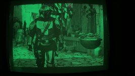
Here is a screenshot of my Mandalorian and Grogu bitmap image - NO Orange spot after the screen dimmed and no orange or green retrace lines between the dots!
I do have some issues with the left and right edges - not completely cleared. That's why I'm going to go through the display calibration again.
Don't worry about the red/orange spot at the top of the photo between Mandalorian and Grogu - I have the 4054A in my theater room and the door to the hall was not completely closed.

Last edited:

