• Please review our updated Terms and Rules here

Cromemco dazzler replica project

OK, I think that is enough for tonight.

We are seeing a cause and effect, but not what I am expecting...

The data bits in port 0Fh appear to be varying the pixels on the screen when they should be affecting the colour.

This makes me think we have a problem further down the Dazzler logic, but it will be easier to diagnose this problem with a working RAM board...

Can I suggest removing the expertly done wire jumpers and reinstall ICs 47 and 55.

Dave
 
In a bit of spare time, can you double check the 157 and 175 ICs on board #1 are correct.

A long shot...

Dave
 
In a bit of spare time, can you double check the 157 and 175 ICs on board #1 are correct.

A long shot...

Dave
Incidentally, I just received my batch of NOS TI 157's and swapped out all 4. No change in behavior though..

Then I just seen this post and noticed one thing, of the 4 74175's, 3 of them are actually 74S175's. Do you think that would matter?
 
74S devices are four times faster than standard 74 devices and draw slightly more current.

While we work out what we are going to do with the RAM board, we can debug the board #1 video if you like. I have a plan already sketched out.

Providing we have a completely white screen with my test program running and with D7 to D0 all 0 (the default) we are good to go...

I also have a plan for your memory board, if you don't mind bending a pin out of a socket and applying a shorting link. Are all the ICs in sockets?

Dave
 
This makes me think we have a problem further down the Dazzler logic, but it will be easier to diagnose this problem with a working RAM board...


Dave
Previously I thought there was because of the way the color encoder works, it is not a suppressed color carrier system as in standard NTSC video, is and in color mode, there is always residual color carriers seen on the video signal even if the balance of them results in what looks like a white or shade of grey.

On the topic of static memory boards, I have also tried another that works with the Dazzler, so the list that definitely work are:

Seattle Computer 16k standard RAM card (I think there is one on ebay currently)
Seattle Computer 64k card SCP-110A
Compupro RAM-17.

When I was making my light pen project (and some tinkering with Matrox cards) I had to learn how to make and use user ports and interface with the bus. So I looked at the design of memory cards. The most simple interface I could find that worked for a memory card, with the minimal number of required support signals from the S-100 bus, to make it operate was the Seattle Computer 16k card. So I based my interfaces with the S-100 bus on that, to keep things as simple as possible, and it worked. If I was asked the question what are the minimum requirements I would say look at the design (schematic) of that card.

In the SOL, due to the limited number of card slots, it is not very practical to use x 3 16k cards, to I went to the 64k ones configured to 48k. One advantage of the RAM-17 is that you can take a memory chip out of it and put in a ROM if you wanted. I decided not to, instead put my ROMs in a gap in high memory (the SOL's 3 brains project).That required yet another bus interface:

www.worldphaco.com/uploads/THE_SOL_WITH_THREE_BRAINS.pdf
 
Last edited:
Providing we have a completely white screen with my test program running and with D7 to D0 all 0 (the default) we are good to go...
Yes that is still the case.

I also have a plan for your memory board, if you don't mind bending a pin out of a socket and applying a shorting link. Are all the ICs in sockets?
Most of the IC's are socketed, but several of the 74LS chips along the bottom are soldered in. I don't mind making minor mods to this board, I have 3 others ;)
PXL_20240401_231017791.MP.jpg
 
  • Seattle Computer 16k standard RAM card
  • Compupro RAM-17

I do have a lot of faith in Dave's ingenuity - but just in case I had to acquire another RAM board, which would you think between these two? I'd like to be to run all the available Dazzler software - I'd be concerned a single 16K board wouldn't be enough for CDOS + the software.
 
74S devices are four times faster than standard 74 devices and draw slightly more current.

Well I found one more original 74175, but that still leaves 2 "S" parts on board 2 for now. I'm checking if the ebay seller can send replacements.
 
I do have a lot of faith in Dave's ingenuity - but just in case I had to acquire another RAM board, which would you think between these two? I'd like to be to run all the available Dazzler software - I'd be concerned a single 16K board wouldn't be enough for CDOS + the software.
No question - the CompuPro RAM17. It's design (like the SCP 16K board) uses the least number of parts, and S100 signals, required for an S100RAM board to work. Both the RAM17 and SCP 16K board currently sell for a similar price on the used market. However the advantage clearly goes to the RAM17 which, on a single board, provides all the RAM that a Z80 system can make use of.
 
No question - the CompuPro RAM17. It's design (like the SCP 16K board) uses the least number of parts, and S100 signals, required for an S100RAM board to work. Both the RAM17 and SCP 16K board currently sell for a similar price on the used market. However the advantage clearly goes to the RAM17 which, on a single board, provides all the RAM that a Z80 system can make use of.
Thanks! Unfortunately Mike D's all sold out of his lot. Will keep an eye out just to have as a backup.
 
No question - the CompuPro RAM17. It's design (like the SCP 16K board) uses the least number of parts, and S100 signals, required for an S100RAM board to work. Both the RAM17 and SCP 16K board currently sell for a similar price on the used market. However the advantage clearly goes to the RAM17 which, on a single board, provides all the RAM that a Z80 system can make use of.
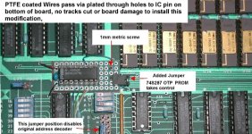
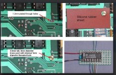
Generally I agree, though there was one thing that made the 64k SCP-110A better for me than the Compupro RAM-17, I needed to deactivate a memory window over 6000h to 7FFFh, I was able to do it by programming an OTP ROM., for the SCP card. I did it with no permanent mods to the SCP card, by running wires then even a tiny screw through existing plated through holes. The card has very attractive INMOS memory IC's on it, and it would be a shame to modify it. I bought a few tubes of those IC's so I had enough for a whole spare set. I needed that memory range knocked out for my Bytesaver board and in that I put BASIC-5 in the ROMs and used a block move program to shift the entire program to start at 0000h, where the program was coded to run and that BASIC version I think uses up memory to nearly 6000h.
 

Attachments

  • SCP110A.jpg
    SCP110A.jpg
    339.5 KB · Views: 3
  • SCP2.jpg
    SCP2.jpg
    820.6 KB · Views: 3
just to catch up with the amendments to the PCB that we have identified.

IC 43 pins 10,13 & 14 - connect to adjacent rail
IC 39 pin 14 - connect to adjacent rail
IC 23 pin 10 - connect to adjacent rail
IC 33 pin 10 - connect to adjacent rail

Cosmetics
R11 should read 30K
Two R23's !
IC 44 should be a 7474
IC52 should be a 7403

Any others identified at this stage ?
 
My initial modification for the RAM board would be as follows. If someone could give this a check over before we perform the modification please...

Bend pin 16 (/DATA STB) out of IC 6C (82S100). This device is 'unobtanium' (apart from off your other RAM boards of course) so treat it gently. Just bend the pin out enough so that it will miss the IC socket but not short against the RAM chip next to it.

This modification will cause the 'G' pins of the address bus latches (7D, 8D, 9D and 10D) to float. Hopefully (as a first test) this will cause the pins of these devices (pins 4 and 12) to float HIGH and make the latches permanently transparent. Having the pins 'float' will not be satisfactory in the long term - but as a quick test it will probably be fine.

Plug the memory card back in and make sure RDOS still works. Run the RDOS memory test to make sure.

If the above works, we need to install a 10k resistor pull-up to +5V onto the /DATA STB signal at a convenient point on the PCB.

If the above does not work, perhaps add a 10k pull-up resistor as a further test?

If the above does not work again, we will have to rethink... Remove any pull-up resistor and re-insert 6C pin 16 in this case and make sure the card works once again.

Making the address latches completely transparent, should configure the RAM board to be similar to other memory boards that do not contain the address latches (i.e. they should not be absolutely necessary).

Dave
 
Thanks! Unfortunately Mike D's all sold out of his lot. Will keep an eye out just to have as a backup.
Hi,

Josh & Mike's new RAM/EEPROM board might work for a RAM board. $35 for a blank.

I currently have a CompuPro RAM 17 in the board set I've been collecting to build a Processor Technology Subsystem B computer into an original Altair 8800 undergoing some minor repairs. My plan is to sell it to somebody eventually, but it's a very slow repair/build so I can afford to work on other S-100 projects in the works.


.
 
Bend pin 16 (/DATA STB) out of IC 6C (82S100).
I think you meant IC 9C, right?

Plug the memory card back in and make sure RDOS still works. Run the RDOS memory test to make sure.
Yep, RDOS runs and passes the memory test. Just for the heck of it I wanted to see what your test app looks like..

D5=0
PXL_20240402_142025183.MP.jpg
D5=1
PXL_20240402_142034127.MP.jpg

I'll have time for the rest of these mods a little later this afternoon.
 
Last edited:
Back
Top