• Please review our updated Terms and Rules here

Cromemco dazzler replica project

Hugo Holden

Veteran Member
Joined
Dec 23, 2015
Messages
4,791
Location
Australia
Finally making some progress on the replication of the original Cromemco Dazzler.

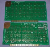
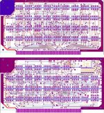
The pcb's were a real challenge. I used my tried and tested method of hand drawing them as a jpg image in Microsoft Picture IT, because I don't have any pcb software.

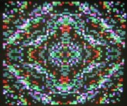
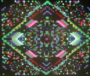
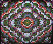
Attached images of the pcb's and some of the exotic diagrams created along the way. Sorry about the reso, had to shrink the files to be able to post.

I went over the design many times to get it as close as possible and error free. (of course not tested yet).

My pcb maker here in AU has a method where he can convert the images into an Altium pcb file, and arranges to get the geometry 100% correct for the IC pin arrays etc.

(There are geometry errors on the S-100 connector on Cromemco's original foil patterns, which is interesting, not enough so they wouldn't work though, but that got corrected).

I decided to "go all the way" with the pcb quality, all gold, pads, tracks and vias. It is an extravaganza with over 70 IC's.

I have acquired all the components, including the original type of Xtal, ceramic tuning capacitor and IC set, but I was not happy with the quality of the IC sockets I could get from local suppliers, so I have ordered gold machine pin original Augat types from the USA which are superior quality.

So with any luck I should be able to assemble it and test it in the next month and start playing with it and the software.

I will post the progress on this thread. Its like I'm back in 1976 assembling the "kit" , I'm sure it would have been just as exciting back then to do it.
 

Attachments

  • DAZPCBS.jpg
    DAZPCBS.jpg
    138.3 KB · Views: 57
  • DAZPCBS2.jpg
    DAZPCBS2.jpg
    216.6 KB · Views: 55
I am looking forward to the results of this Hugo.

I have a Cromemco Z2, and one of my ‘wants’ was a Dazzler for it.

Shall I start assembling a kit if parts for one?!

Dave
 
Following up on your previous discussion... have you found a source (or an alternative) for the hard-to-find Fairchild F3342 shift register?
 
Following up on your previous discussion... have you found a source (or an alternative) for the hard-to-find Fairchild F3342 shift register?

When I was looking into the TMS3417 which is very difficult to find, but I found a few in Germany, I found two other alternatives, The 74HCT7731 :

https://www.ebay.com.au/itm/Lot-of-...m3fa41dc4bf:g:d-sAAOSwLmlbO7aM&frcectupt=true


Also the Fairchild F3342DC , which I found a few on ebay too:


https://www.ebay.com.au/itm/F3342DC...955565?hash=item41e1032b6d:g:~28AAOSwaaJa6NFO


the HCT parts had a different pin-out so I considered an adapter.

The F3342DC, I had initially discounted as a possibility, the reason being that it is a 2MHz rated part, and the TMS3417 is a 5MHz part so that I considered F3342DC might not be fast enough for the application and not having the Dazzler boards working in front of me on the bench yet, I was not sure if it would work. However, in the Practical Electronics article from 1976, they used the F3342DC (rather than the TMS part that Cromemco specified in their manual) so I concluded that this must mean two things; the TMS3417 was probably difficult to get in 1976 as well and the F3342DC must have worked on the Dazzler pcb as a direct substitute.

When I have it up and running I will be able to test these three IC's.
 
Thank you for the detailed explanation of the work you've done to track this part down.

As you pointed out the PE article specified the F3342 however all pictures I have seen posted to the web, as well as the actual Dazzler I own, have the TMS3417. The results of your testing of these different parts will be interesting.
 

Yes, I had seen that very interesting project before and it looks to be very well done.

However I was attracted much more to the original Dazzler design, partly because of its historical significance in the field of S-100 computing and the fact I can work with standard 74 vintage TTL etc, I find it is very amenable to fault finding & repairs. Also I wanted to find out for myself just what could be done with the original Dazzler.

I have written up articles on the Matrox ALT256 and ALT512 video cards, these are being published in Silicon Chip magazine starting next month. Hopefully, the Dazzler will follow sometime (assuming I get it working !)
 
I could have mentioned that when this Dazzler replica is finished, I will be attempting to run it in my Sol-20.

I had seen a post in the past where a Dazzler was tried in a Sol-20 and it didn't work.

When I was working with the Matrox ALT512 I found something interesting that stopped that card working properly in the SOL-2. In the Sol, they hijacked the PRDY control line and drove it with a tristate buffer for the Sol's own activities. This interfered with the Matrox card's use of that line and caused it to malfunction.

On researching the different versions(revisions) of the Dazzler, I found the early ones used the PRDY line too, but later they abandoned it, certainly by revision C of the pcbs by the late 1970's. So probably there were complaints about Dazzler compatibility with various S-100 computers I would suspect (probably the Sol) so Cromemco modified the design. The track work on the earlier boards has a number of differences to the later ones. So I went with the latest design rev C. So it appears all the Dazzlers were not born equal.

It is important of course for the Dazzler that the computer is fitted with fast static ram.

So far, after examining the version of the Dazzler I'm building, it should work in the Sol, but I doubt if the earlier versions would have.
 
The Dazzler replica is coming along better than I expected. The Augat sockets finally arrived and I fitted the IC set.

Given the complexity of the boards & tracks and the number of IC's I was bracing myself for some hardware errors to repair, however there appear to be none... yet. All the work double checking the track layouts with the schematic paid off. The original foil patterns were poor photocopies and had a lot of ambiguities.

It is up and running, it took me a while to figure out how to work its registers to get control over it. One interesting thing is that its DMA activities upset CP/M and there is a conflict of some kind, not to do with the address field of the image, so I cannot have it active while running CP/M but it does not in any way appear to affect the operation of SOLOS or the function of the SOL-20 computer.

Because it took so long for the IC sockets to arrive, I had time to spruce up a baby color video monitor with a 9" diagonal screen to use with it.

The attached photo shows the Dazzler in the 512 byte mode just looking at random memory data, so multi-colored blocks appear. I have yet to write some programs to manipulate the memory and get more interesting patterns.
 

Attachments

  • dazpic1.jpg
    dazpic1.jpg
    152.6 KB · Views: 18
  • dazpic2.jpg
    dazpic2.jpg
    130.7 KB · Views: 18
Neat...

It's amazing how excited people can get (me included) by the sight of random coloured blobs on a CRT :)!

Keep up the good work Hugo.

Dave
 
Yes. Very nice work. Great to relive 1976 microcomputer color graphics capability. Was there ever a BASIC version that utilized the Dazzler?
 
I'm trying at the present to get the Kaleidoscope program working. I'm still not certain that all the hardware is 100% good, although when I manipulate the registers it appears to do what the manual says it should, with the modes of operation and the location the picture is started in memory and turning it off & on etc.

The board/s certainly interferes with the operation of CP/M and disk access locking up the computer, due to the DMA I expect. Yet the original program I think was made to run under CP/M. So I'm doing various experiments to try to get to the bottom of it. Just running it with Solos in the Sol-20 is not causing too many issues.

If anyone has a SOL-20 running CP/M from a disk drive and an original Dazzler to try in it, I would be interested to see if the effects are the same.

BASIC is very convenient testing it, writing to the ports etc. I have not seen BASIC Dazzler programs, but there might be some.
 
"Holy Cow" I just got the Kaleidoscope program running. The hardware is good. There were some issues with the code. I relocated it to 0100h and altered the picture starting address. I made it into a .COM CP/M program, it runs fine inside CP/M now and if I exit CP/M it remains in RAM and I can also run it in solos by typing EX 0100.

Its one of the most mind blowing and artistic displays I have ever seen, it seems forever changing and varied. It is psychedelic and mesmerizing, like somebody put LSD in your coffee. I asked my wife to come into the workshop and look at it and we just stared at it for ages. That is a great reward for all the work making the boards. Now I just have to figure out how they did that with what looks like a relatively small program !

I will post a you tube video of it soon.
 
.......I just had a look at the video of the Kscope program on S-100 computer's website. It appears to run faster or be more frenetic than in the SOL-20 where the pace of it seems a little more sedate and hypnotic. Probably the Cromemco ZCPU runs faster than the 8080 in the Sol-20, or is it the same approx speed ?
 
Nice work (again) Hugo.

I can’t wait to see the video. But do it justice...

Dave

Yes, it will take some effort to get a good recording, but since its NTSC composite video I may be able to record it directly and make a video file.

In the meantime I found that when I exit the Dazzler with a Solos reset, the image at that moment remains in RAM, so I wrote a tiny program of a few bytes in another part of memory to switch the Dazzler back on, so I can see the last "frame" that the Dazzler made before it was deactivated. I have attached some screen photos.
 

Attachments

  • dazpc1.jpg
    dazpc1.jpg
    249.8 KB · Views: 12
  • dazpc2.jpg
    dazpc2.jpg
    248.5 KB · Views: 12
  • dazpc3.jpg
    dazpc3.jpg
    248.7 KB · Views: 12
Last edited:
Out of curiosity, do you have any software that runs in the 4x resolution B&W mode? I'm wondering what the 128x128 pixel mode looks like. (Did anything actually use it?) Mainly I'm wondering about both modes... is the active video field 256 lines out of the possible 262 in height? I imagine a fair bit of it must get cut off in the overscan on a typical CRT, which leaves me wondering what the "effective" on-screen pixel resolution is. In color 64x64 mode are the color pixels three pixels tall (192 lines) or four (256)? I assume it must double-scan the 128x128 in the 4x mode... or is that rendered as just a "letterboxed" strip?

Since you mentioned the Matrox ALT-256... is there much software out there for that? I was kind of wondering if I might be able to emulate it without too much trouble with the video processor idea I've been working on. According to the manual it works by setting individual pixels by receiving X/Y/on-off coordinates via I/O ports, there's no "direct memory access"? Is there any delay in this process with the card, or can the CPU ram pixels in at full speed with no wait states?
 
Back
Top