• Please review our updated Terms and Rules here

New PDP-11/53 Build

Steve Toner

Experienced Member
Joined
Apr 7, 2020
Messages
171
Location
California Central Coast
I recently acquired a KDJ11-DB board which appears to be from 1991, based on the date codes on the chips. Put it together with an H9278-A backplane, MeanWell RD-85A power supply, a 3U rack mount case from Circuit Specialists and homebrew front & rear panel (or cab kit to use the DEC term) and here is the result:
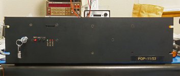
Front View.jpg

This may offend the purists, but finding a proper DEC enclosure is a bit problematic...

The keyswitch controls boot select jumper W22 so that if jumpers W2, 3, 5, and 8 are installed, it will autoboot with the switch off and enter console mode with the switch on. The slot above the LEDs is for an SD card - I am planning to use Peter Schranz's RLV12 emulator to provide mass storage.

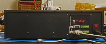
Here's a rear view:
Rear View.jpg

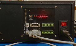
If jumpers W2, 3, 5, and 8 are left unjumpered then the boot option switch can be used to select the desired boot option. I didn't do a fancy hex display for the status LEDs, but instead brought them (all seven of them!) out to individual LEDs. Baud rate for the two serial ports is selected by a rotary switch and the currently selected rate is displayed on an LED character display. These displays are entirely optional, and the rates corresponding to each switch value are printed on the board.
Rear Detail.jpg
The LED displays don't photograph well, but they do look very nice in real life.

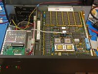
Interior layout:
Interior.jpg
The backplane is mounted using some scrap alumim(i)um leftover from other projects. The card guides are machined from acetal.

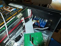
Detail view showing LTC module, front panel, and power connections to backplane:
Interior details.jpg

The LTC is generated with an optoisolator, and the front panel signals are generated by a PIC16F1615 microcontroller. The raw LTC signal is fed into a Schmitt Trigger input on the microcontroller and regenerated before being sent to the bus. This may introduce some jitter into the signal (but coming from the power line, it's probably got plenty of jitter to begin with), but it allows the microcontroller to detect a loss of power by the absence of LTC edges and generate the aprropriate power-down sequence.

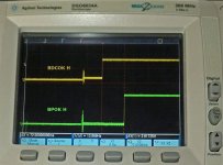
Power up sequence. Note the 72msec delay between BDCOK and BPOK:
Power Up.jpg

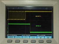
Power loss detection. BPOK is dropped approximately 50 msec after loss of BEVNT (LTC) signal:
Power Down 1.jpg

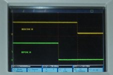
and then BDCOK drops about 4 msec later:
Power Down 2.jpg
The power supply is supposed to have enough reserve to allow the system to run for at least 3 msec after BPOK drops. With this configuration (just the CPU board installed), there is approximately 100 msec of reserve...
 
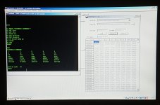
...and while I wait for my USB JTAG programming cable to arrive so I can program the CPLDs on the RLV12 emulator, I'm stuck loading code over the serial port. I've been unsuccessful getting tu58em to work - tried 3 different machines (Windows 95, Windows XP and Windows 10) and all failed for different reasons. But I am able to load and run paper tape images with pdp11gui, so have verified operation by running BASIC...
pdp11gui.jpg
 
This may offend the purists, but finding a proper DEC enclosure is a bit problematic...
Well, there are things you can do to improve your homebrew enclosure. For example, it appears to be entirely missing the Digital Equipment Corporation Logo, which, yes, doesn't seem right. Adding that, even if you don't get it perfect, will really help with making the purists happy, I think.

I encountered a similar situation with my laptop, but I managed to solve it without too much work:
apple-laptop.jpg
 
Hi - FYI, forced air cooling across the boards ad backplane is NOT optional. DEC had 2 fans of at least 100cfm cooling the boards and PSU - you will drastically shorten the life expectancy of any board used without cooling in this manner.

Please sort the cooling arrangements and save the vintage cards and components from premature failure.

Also - only using 2 wires for +5V and ground will rapidly cause connector issues if additional boards are added. Those connectors need the current splitting across many pins to be reliable and not overheat if more boards are installed.

Robin
There's a fan. You can see the power leads to it in the interior view photo.

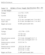
The power supply can only supply a maximum of 8A@5V, so two wires should be plenty. I'll check the rating on the connectors, but I'm pretty sure they're up to the task. This is not going to be a big system - just the CPU board with its 1.5MB of RAM and the RLV12 emulator. The only other card I can imagine installing is a parallel printer card, but I think it more likely that I'll just use the second serial port to attach a printer.
 
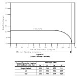
OK, the connectors are rated at 11 amps:
current capacity.jpg
I derate this by 50%, and 2 wires should be sufficient to carry the 8A maximum that the power supply can provide, plus (on the ground side) whatever +12V current is required. Also, 18 gauge wire has 10 amp capacity at a 60 degree C temperature rating (ref: https://en.wikipedia.org/wiki/American_wire_gauge)

I'm pretty sure I made these calculations up front and didn't just randomly choose to use 2 wires, but it's always good to go back and review in case I made bad assumptions or overlooked something. Plus it provides a heads up to anyone who, 5 years from now or whenever, might stumble across this thread and decide to attempt a similar project...
 
Bear in mind that DEC had overheating issues with a 36A supply split between all the connectors... Also - voltage drop to the backplane is critical - the DEC PSU is specced at 5.1V out...

FYI, I have spent a lot of time repairing DEC backplane and PSU connector solder connections that have completely degraded over time, to the point of detaching from the board completely when dismantled in one case...
1713203075606.png
 
Last edited:
Hmmm... there are 6 +5V pins, so in theory 36A spread across those 6 pins (100% connector loading) is within spec (should be good to 6.64A per connector based on the connector chart, and assuming AWG18 wiring). But there's only about a 10% margin there, so I could see how a flaky connection could lead to problems...

My power supply output measures 5.0916V under load (this is just the processor board right now, sitting in ODT) and I measure 5.0588V (dropping to 5.0576 running continuous self-test) at the board, so only about a 33~34mV drop under current conditions.

Processor and gate array chips are running at around 30° C (21° C ambient room temperature, running continuous self-test running for 10 minutes or so). Power supply temperature is also about 30° C.
 
That's not sounding too bad, I'm surprised the CPU is not running warmer! - if you still have the original DEC connectors with the square pins, it's common to get a blackened or pitted row of marks on the pins where the one side of the connector mates, which can get hot - they used the same connectors on other things (VT240 terminals spring to mind) and brown charred connectors were not unusual...

I was looking at power problems last week on my non-DEC chassis, (It is quieter than my BA23) I was having issues with a ZuluSCSI card being seemingly unreliable (For clarity, the ZuluSCSI is NOT to blame!) - They can be powered via SCSI termination, and with a DC power connector (3.5" floppy type) and with the extra power connector in place, I was seeing issues (The QBus Emulex SCSI card had a varistor on the terminator power for overload protection, so I added the extra power option as there was some drop across it...)

Removing the power connector - the problem seemed to go away.. I had already ruled out the SCSI card and ZuluSCSI, SCSI cable etc. but measuring between the ZuluSCSI GND and the disconnected power plug, I had 35-36mV - no problem I thought... so I put my meter on the 10A range and measured current between the same two grounds... 0.25A! OK - now I see a problem...

The 11/73, 4MB RAM, SCSI card and serial ports were drawing over 8A on the +5V, and the SCSI cable and extra power connector to the ZuluSCSI were providing a second return route to the PSU ground - and weird SCSI problems....

That system has something like 4mm^2 cables for the GND and +5V, with voltage sense feedback to the PSU from the backplane, so a REALLY good ground to the backplane is a good idea - and they usually have more ground wires than +5V on the DEC backplanes like the BA11N and BA11S...

I didn't know what the fan wires were for in the photos! - I do like systems to run cool - I use bus grant cards where possible to space the boards out for better cooling, and move the CPU into the second slot if space permits - you can use lower fan speeds and still get the boards cooler than when in adjacent slots, it's a win-win

Robin
 
My first attempt at running with the RLV12 emulator have not gone well. I've got no output on the breakout board serial port - this could indicate a cabling problem or a problem with the ATMega1284P microcontroller. I used a TL866CS MiniPro to program the microcontroller, so I don't have 100% confidence in the results...

I used an ATDH1150USB to program the CPLDs, and that appears to have worked successfully. When I issue a MAP command in console mode, addresses 17774400-17774416 appear in the list. However, the CSR shows a value of 102200 (Operation Incomplete Error, Controller Ready). Also, at initial power-up an unexpected trap to 160 (the RLV12 interrupt vector) occurs, presumably as a result of the error condition being set. This is also making me suspect that the microcontroller may not be operating correctly.

More to come...
 
Ooh good luck with the RLV12 emulator - my real RLV12 is faulty and not got round to trying to fix it yet.. I get lost on that guys site - he says the emulator is available but I can't see where from, lol...

Does it expect a particular file structure or format on the SD-Card?
 
Yes, he has instructions for formatting the SD card from a Mac (which I don't have). Each virtual disk is a separate partition of 20840 sectors of type "Linux". I used a Raspberry pi5 to set up (or attempted to set up) my SD card, but I don't think it's getting far enough to read it... I'm assuming that there should be some TTY output even if no card is inserted in the drive slot, so that's where I'm focusing my attention at the moment...

btw, "that guy" is on here - he's user cbscpe - but he doesn't post frequently...

As far as availability goes, I don't think he is selling the cards of full kits, but he has the gerbers available on his website. I downloaded them and sent them off to JLCPCB to make a batch for my use...
 
Last edited:
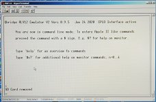
Making progress...

splash screen.jpg

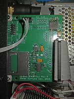
Who had "mislabeled PC board" in the pool? I had connected the PC serial port to SLU0 originally. Looking at the Tx pin of (TTL level) USART0 (JP1) showed activity, but it didn't show up on the Tx pin of (RS-232 level) SLU0 (SV3). Because for some reason USART0 goes to SLU1 🤯 With the laptop connected to SLU1, the above splash screen is properly displayed...

Break Out Board.jpg
 
Some minor progress... I started with a 32GB SD card but couldn't get that to work at all with the emulator. So dug out an old 2GB card and with that I am able to create blank partitions that it recognizes and loads. However, if I copy a disk image to one of these partitions it won't boot from it. Also, I haven't been able to get it to recognize the DOS partition. You're supposed to be able to mount a disk image file from a DOS (FAT16 or FAT32) partition as an RL drive and then boot from that. Like an XXDP to run diagnostics or, even better, an RT-11 install disk which can then install a system on one of the "native" partitions...

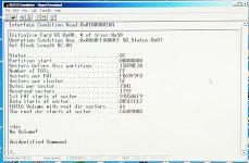
I've now formatted the SD card so it has only a DOS partition. Tried the full 2GB and when that didn't work, tried again with just a 400MB partition. Still no luck. I've tried formatting it using Windows 7 and Linux. The values that the emulator reports for the partition are bogus and I'm not sure what the problem is, but maybe uninitialized Volume Boot Record (VBR). In looking at the ATMEGA code, both the MBR and VBR must be OK for the DOS volume to get loaded...

FAT16.jpg

More to come, but it may be a while before I can get back to this...

Edit: wrong hex file? The output seen here doesn't match the source code. Also, the "fdisk" command is missing from this version. Missing in this display is "Partition size" after "Sectors before this partition" Also, this set of messages is only printed if the call to MountVolume indicated success, so the dir command should not be reporting an error.
 
Last edited:
Hi - On my ESP32 projects with SD cards, I found it best to use cards between 4GB and 16GB - both larger and smaller ones had problems, there are many variations in the feature set - also , I would try a single FAT32 partition unless you see reason not to.

I take it you have found working 10MB RL02 images to try?
 
Hmmm. Maybe you can ask the developer to send you an SD card image which you can DD with your linux box on your sd-card?
Thanks a lot for the link to the RLV12 emulator project, this sounds really interesting.
 
Hmmm. Maybe you can ask the developer to send you an SD card image which you can DD with your linux box on your sd-card?
Thanks a lot for the link to the RLV12 emulator project, this sounds really interesting.
I think I have to resolve the issue of the hex file not matching the source code first...

And hopefully my stumbling efforts will save other people time and effort if they decide to try building one... It'll be pretty nifty when (if) it works, but there appear to be a bunch of pitfalls along the way (like SD card size)...
 
Here's the latest:
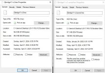
The posted source code and the hex file for the RLV12 emulator do not match. The source code won't build, as it tries to include a file named print-v1-2.asm, but the file that is there is print-v1-1.asm. If I change the include line, then it compiles but the resulting size of the hex file is different than the hex file that is there. Strangely, the hex file I build is smaller than the posted one, though perhaps this has something to do with print-v1-1.asm vs. print-v1-2.asm.
hex files.jpg

As I am currently at an undisclosed location away from the PDP-11, I can't try the firmware that I built to see if it works better than the prebuilt image...
 
Back at it... Tonight I tried (using same old firmware) a new 8GB SD card formatted as FAT32. It gives Error ID 82, same as the 32GB card. Formatting the 2GB card as FAT32, it acts the same as with FAT16. So it appears that what I've got running right now does not like SDHC cards (even though the photos on the developer web page show an 8GB card installed).

So it looks like I'll have to try reprogramming the ATMEGA...
 
Back
Top