I was being a little tongue-in-cheek there, and I think you misread a single letter in one or two places in what I wrote.
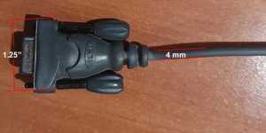
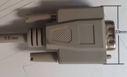
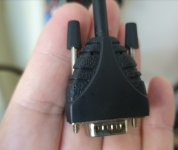
Yes, a DB-25 connector is about that wide. A DB-9 connector (if such a thing even exists) would be the same width, because it's also using a "DB" shell. If you want a smaller connector, you need to switch to, e.g., a "DE" shell, which is a bit over a centimetre wide.
For reference, here is a comparison of the standard shell sizes.
View attachment 1278360
Note that there can be different connectors with different numbers of pins using the same shell size. For example, the connector commonly called "VGA" is a DE-15 connector. It's quite different in size from a DA-15 connector, also used for video. And I have friends who have ended up with the wrong part because they weren't paying attention to what they were ordering.
I am not surprised, since this seems to be the most frequent arrangement, but I am not sure that the standard specifies it. Perhaps it does, since RS-232 doesn't use differential signals, so there's the potential for a ground loop over the ground pin anyway. I don't really know enough about this to be sure.
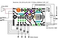
But what I do know is that shields are not designed to carry signals, and thus are probably even worse to use as a ground reference. A moving ground might not be such a bad thing on an RS-232 connection, since the signals are digital and swing quite far past the ground in either direction (minimum ±3 V, but usually about ±12 V). But you're running analogue signals over this, which I think could be affected by even small changes in the ground level at the joystick vs. the computer.

 I have no problem with it.
")