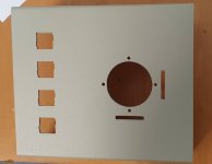
I am interested in a "how to". I've done similar sheet metal work, but nothing quite as complex as the cutouts this project requires.
In the case of these holes, I decided the better method was to cut them from the inside of the housing and work largely from the inside with the outside face on a flat surface. One problem is marking holes in a way that makes their borders clear and is resistant to the effects of filing nearby. If the hole border is not clear to see, its not possible to easily file it out to the correct position.
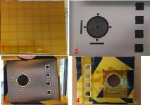
The we are dealing with a pre-painted panel, so all care must be taken to protect the paint. I applied initially two layers of polyimide tape, it sticks well enough, but not too sticky that it removes paint. Many tapes leave residual glue on a surface, it does not. Then I applied some heavier plastic tape over that Photo 1.
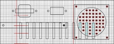
Photo 2: To mark the holes to be drilled I applied a decal on the inside. This was done in a drawing program. The holes to be drilled had a small central white dot. If you zoom up on this photo you will see those dots in the decal and this entire pattern was laid out over a 1/16th inch grid with a transparency effect, then that grid was deleted last thing from the image. The decal was applied, and I heated it in the oven to 75 degrees for 1/2 an hour, and after that applied the duplicolor clear spray over it. This made the decal super stuck to the panel and not affected by filing.
Then a scribe was used to create a small mark on each white dot. Then very carefully, a 1mm drill , held in a hand pin chuck was used to start each hole. After that all of the holes were initially drilled with 1.5mm pilot holes in the drill press with high magnification to make sure each hole started on the small indent provided by the 1mm drill tip. Once they were all inspected, they were then all drilled out to 3mm, except the ones for the two 1" long x 1/8" slots, these were drilled out to 2.5mm diameter. As shown transilluminated in photo 3.
It is very important to inspect the work after the 1.5mm pilot holes are drilled, if any hole was out of position you can choose then to drill it out to a smaller diameter and solve the problem that way.
After this some small needle nosed side cutters are used to cut between the holes.
Photo4: It is very important after the holes are done to trim the tape away from the hole edges and apply fresh tape on the painted side of the panel near the hole edges. What happens is the drill pushes the tape a little away from the surface and swarf gets under the tape edges, this can mark the paint if it is not removed. This issue is always worse if you are drilling toward a painted surface rather than through it initially.
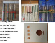
Photo 5: an assortment of files are used , a large round type A. One the large hole is filed, some 600 grade paper is wrapped around a cylinder and used as a tool to smooth the hole edges and remove the tooling marks from the edges.
For the square holes, the file I used is a flat type, B which has no serrations down its sides, this makes it very easy to file out a rectangular hole. When filing is being done, from time to time, apart from looking at the decal markings, the geometry is checked with the dial calipers. The 1/8" wide slots were done with the small flat needle file C.
File D is a 3mm square section needle file, used to finish ends of the slot holes.
All of the rectangular holes are then finished with the needle file E which removes most of the tooling marks from the other regular files. Then file F is used to start the small rectangular sections in the sides of the square holes, until file E (which is 4mm wide) just fits, this is used to finish those. Also at the finish, the rectangular hole cut edges are additionally smoothed with some 600 grade paper wrapped around the needle files.
Then the issue of how to remove the remainder of the decal: I use some Citri-strip paint stripper applied a thin layer very carefully with an artist's brush and very sparingly just to the decal surface, not enough to pass into the holes. The decal turned to goo very quickly and most of it removed with a plastic scraper, then after that the panel was washed, the tape removed and the inside of the panel cleaned again with a cloth and contact cleaner and the hole edges also cleaned with cue tips and contact cleaner.
No doubt all of the above explains why it is better most of the time to send the work to the local CNC shop !