• Please review our updated Terms and Rules here

Cromemco JS-1 Joystick Replica

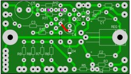
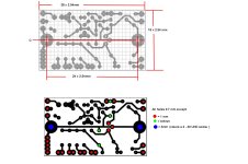
I built a home made proto pcb . (In lieu of plated through holes on a proper pcb where wires pass into a pcb on these home made ones I use 1.5mm brass eyelets)

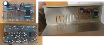
I will test it out today. I want to run it up with an actual OP amp driving the the audio system, rather than a signal generator, just to make sure everything is 100% ok.

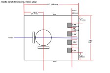
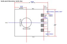
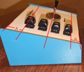
There is plenty pf room for it on the rear of the housing, the inside dimension of that housing there is about 59mm tall and the pcb there is about 41mm.
 

Attachments

  • pcb1.jpg
    pcb1.jpg
    219.7 KB · Views: 11
I have attached the info required to make these boards.

Since the audio output with the 8 Ohm speaker has about x3 the power of the 45 Ohm speaker system, it possibly could be a tad loud. So I added a link on the pcb where a resistor could be placed at the input, in series with the audio input feed. Since the input resistance of the output stage is around 500 Ohms, a series 470 Ohm resistor (for example) would cut the speaker drive voltage in half and the audio power would drop to 1/4.

The resistors in series with the + voltage feeds to the joystick pots can be used to alter the range of joystick voltage. I found with the Joysticks I took from my Kraft controller, that 1k resistors were suitable to give +/-2v. But it might be a little different for some other Joysticks, at least we can adjust the dynamic range with these resistors.

Also, I think the "+/-18V supplies" from the S-100 computer backplane, being unregulated, could be in the range of 15.5 to 18v (depending on the line voltage), this board will work fine over that range of voltages.

Again, the purpose of this board is to allow the use of easy to get 8 Ohm speakers and at the same time boost the audio power and allow some calibration of the non-original Joystick pots, and eliminate the need for the +/- 5V voltage supply feeds to the unit. This reduces the number of conductors required in the cable.
 

Attachments

  • PCBxBOM.jpg
    PCBxBOM.jpg
    318.1 KB · Views: 8
  • PCBxDIM.jpg
    PCBxDIM.jpg
    260.2 KB · Views: 8
Last edited:
Wow this looks great! really well done. Unfortunately the one attempt I made at etching a homemade PCB in the 90s went horribly (with a kit I think I bought from Radio Shack) and I haven't tried again since. Would it make sense to use a trimmer pot for adjusting the volume?
 
Finally got my enclosures. Here's a side by side comparison to the original. Width & Depth are virtually identical. The Hammond enclosure isn't as tall - but we already knew that. The blue colors basically match. The Hammond is a little more cream color compared to the Cromemco's off-white. But for an off-the-shelf part, I think it's pretty close - I'll be happy with them.

PXL_20240425_203206035~2.jpg

PXL_20240425_203144417.jpg
 
Wow this looks great! really well done. Unfortunately the one attempt I made at etching a homemade PCB in the 90s went horribly (with a kit I think I bought from Radio Shack) and I haven't tried again since. Would it make sense to use a trimmer pot for adjusting the volume?
It could , but I think we will find out when it is running if the volume required adjusting down, it may not, but at least there is space to add a resistor if required.

From the photo, it looks like dimension A is greater than B for the joystick and knob array . Can you measure the originals and document where the holes were? we may need to reverse those dimensions to fit the Kraft Joystick to the Hammond enclosure.
 

Attachments

  • Box.jpg
    Box.jpg
    97.9 KB · Views: 2
Last edited:
I did some measurements and calculations, using the internal dimensions of the Hammond box, Some of the measurements don't exactly match the calcs because the folds in the metal are not perfect, and it slightly affects the inner dimensions, it is close enough to within half a mm or so.

The calcs confirm, if we want to, we can mount the Kraft Joystics on the center line of the panel. I think that is where we should put them to keep the front panel symmetrical looking , though I'm not sure yet, where on the horizontal (left-right) axis we should position the button holes and Joystick hole, probably copy the original on that.

Worst case the Kraft assembly would just fit if the dimension was about 62 mm (measured from the inside front edge toward the inside rear edge ) and it was closer to the front edge than center, but the center line is at 69.5mm, so it fits with some clearance if we put it there, right in the middle line. I also checked with a mechanical gauge and it appeared to match the calcs, but please check them in case I fouled it up.
 

Attachments

  • Jdim.jpg
    Jdim.jpg
    168.2 KB · Views: 4
Last edited:
The calcs confirm, if we want to, we can mount the Kraft Joystics on the center line of the panel. I think that is where we should put them to keep the front panel symmetrical looking , though I'm not sure yet, where on the horizontal (left-right) axis we should position the button holes and Joystick hole, probably copy the original on that.

Yep doing a test fit with my Kraft joystick on the Hammond case, we can easily mount it centered. We could even move it forward 10mm or more if we wanted to. My guess on the original though it was mounted forward to accommodate the hand on the somewhat tall enclosure. Ours doesn't have that issue, so I'm I'd be fine with mounting it center front to back.
 
@nullvalue, can you check the attached diagram and see if you agree with the placing of the holes.

Since the panel on the Hammond enclosure is a little smaller in size, some scaling had to be done to keep the proportions similar so it looks like the original, except we are putting the button & joystick array centrally rather than a little offset toward the front, as it was on the original unit.

Also note that the front to back dimensions are measured from the inside of the panel. They are a tad ambiguous, +/- 0.5mm because of the folds in the metal. I think though, when the holes are cut out, with a CNC router, it will need to be done from the inside surface, because the panel will require to be clamped to a flat surface. Though it could be done from the top ( outside painted surface) with more involved clamping to level the 10 degree slope. In any case all the holes could be referenced to the panel center rather than the edges, in conjunction with the L & R panel sides.
 

Attachments

  • panelj.jpg
    panelj.jpg
    127.9 KB · Views: 1
@nullvalue, can you check the attached diagram and see if you agree with the placing of the holes.

Since the panel on the Hammond enclosure is a little smaller in size, some scaling had to be done to keep the proportions similar so it looks like the original, except we are putting the button & joystick array centrally rather than a little offset toward the front, as it was on the original unit.

Also note that the front to back dimensions are measured from the inside of the panel. They are a tad ambiguous, +/- 0.5mm because of the folds in the metal. I think though, when the holes are cut out, with a CNC router, it will need to be done from the inside surface, because the panel will require to be clamped to a flat surface. Though it could be done from the top ( outside painted surface) with more involved clamping to level the 10 degree slope. In any case all the holes could be referenced to the panel center rather than the edges, in conjunction with the L & R panel sides.
This looks great to me. @DougM is this everything you'd need to create the .DXF?
 
Thanks @labomb. Looks great

just a few things; The line (cathode) ink markings on D1 & D2 need to be switched, and there was missing track and a white ink mark for one of the links.
 

Attachments

  • pcbb.jpg
    pcbb.jpg
    180.2 KB · Views: 2
We could even move it forward 10mm or more if we wanted to.
The calcs & diagram shows the max amount we could move it forward, from center line toward the shallower end of the Hammond cabinet, and it still fit (just) is 7.4mm. But I agree with you, best to keep it exactly on the center line. We were lucky this worked out so well with the combination of the Kraft Joysticks and Hammond enclosures.
I think, probably the original enclosures were made by Hammond too.
 
I marked up Doug's drawings with the actual measurements - sorry I took them in inches :)
I'll update the drawing and post the DXF

LMK how you want to move forward - cut up an actual box, cut a sacrificial plate or laser up some cardboard?
 
There were some dimensional errors on the first panel drawing, where the numbers didn't add up.

For my panel, since I will be doing it by hand, the holes will be laid out as close as possible on a 1/16" grid.

At least the two lines that position the switch hole edges and the left right spacing of the joystick are on a 1/16 grid, and the spacing of the switch holes vertically are now 7/16 apart that helps. The switch holes themselves though have those odd sizes and if they are imperial their holes would be something like 75/128 inches tall, or 0.586" or 9.376/16 or 14.884 mm tall.
 

Attachments

  • panelj.jpg
    panelj.jpg
    140.7 KB · Views: 3
I'll update the drawing and post the DXF

LMK how you want to move forward - cut up an actual box, cut a sacrificial plate or laser up some cardboard?
Good idea to cut up some sacrificial plate I think. Only get the one chance with the real box.

One thing, I do not have the actual switches yet. It will pay to measure those switch bodies, just in case the dimensional drawing we found is not ideal.
 
Thanks @labomb. Looks great

just a few things; The line (cathode) ink markings on D1 & D2 need to be switched, and there was missing track and a white ink mark for one of the links.

Ahh... sorry about that. The diodes were a bit difficult to discern. One more for review... I'll upload the gerbers when you give the okay.

Cromemco_JS-1.JPG
 
I'll update the drawing and post the DXF

LMK how you want to move forward - cut up an actual box, cut a sacrificial plate or laser up some cardboard?
I can send you the enclosures and include the switches and joysticks so you can test fit. Obviously cutting a test sheet would be ideal first, would you like me to look for and include an aluminum plate of some kind? Or do you have a piece of cardboard that would be an accurate enough test?
 
We were lucky this worked out so well with the combination of the Kraft Joysticks and Hammond enclosures.
Regarding the Kraft controllers, did you happen to find a source for the centering spring? I think we both may need one each.. I sent some emails to a few online sellers who seemed to specialize in these but haven't heard back.
 
Regarding the Kraft controllers, did you happen to find a source for the centering spring? I think we both may need one each.. I sent some emails to a few online sellers who seemed to specialize in these but haven't heard back.
I had a few assorted springs and I managed to cut one to work and feel the same as the other. I'm not sure where to get a definite part though. I'll look around and see.
 
Last edited:
Back
Top