• Please review our updated Terms and Rules here

1084 monitor cooking one particular resistor

Witchy

Experienced Member
Joined
Oct 11, 2015
Messages
376
Location
Flatlands, UK
Hello folks,

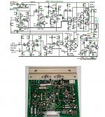
I've got this 1084 on the bench, sent to me because it went CRACK and the picture collapsed so there's obviously a fault in the vertical deflection circuit. Looking at the board the culprit was R346 which according to the schematic is a 4.7ohm resistor. Something prior to it is feeding it too much and it burns up, I verified this by replacing it and filmed it smoking.

Has anyone come across this before? Given the rapid failure of R346 when it's replaced how can I go about measuring the rest of the circuit other than removing components and testing them out of circuit?

Here's the relevant part of the schematic:
1084-monitor-vertical-deflect.jpg

Cheers!
 
I thought of that, it's the outer winding of the deflection coil and measures 12.7 ohms. I did ponder if the whole deflection chip (IC302) had shorted but pins 5, 6 and 9 should be be protected against that, according to the datasheet. Pin 5 is an output with a max possible voltage of 60V and its output is derived from the flyback generator at pin 7. I need to look for references to '23' and '24' to see where those outputs go because shouldn't D346 prevent output voltage from hitting R346 and making it burn? Maybe I'm looking in the wrong place entirely, though there's definitely still a fault present in the vertical deflect before R346 burns up.
 
My thinking was an open coil on S348 would cause all the current to flow through the resistor, instead of whatever normal proportion of it. You'd have to take it out of circuit to find out if it's open, otherwise you're just measuring the resistance of the rest of the circuit.

I think what I said is true as far as it goes, but I really couldn't say how likely that failure mode is vs. some other potential one.
 
OK, maybe 12.7 ohms isn't enough? Time for a search to see if anyone else has measured the coil resistance. This pic shows S348, or at least my understanding of what S348 is with 3M5 and 4M5 marked. I'm still tracing the solder side of the board alongside the schematic to see what's actually connected to what.

IMG_9691.jpg

Cheers!
 
Also The '+26' is confusing me around that circuit. I originally thought it was referencing 'point of interest 26' in the circle but looking at the rest of the drawing and the datasheet for IC302 it's actually a 26V voltage with R344/R346/R367/R363 being pullups. It ends at pin 9 on IC302, the supply voltage. Could it be possible that something is making that voltage much higher than 26V? I'm still tracing the board to find its origin.
 
pin 5 is a boosted DC supply for the vert output amplifier. I would say IC302 is shorted. I think the 26V supply comes out of the SMPS mislabeled as 265V
but that feeds other circuits so I would assume it's ok.

Larry G
 
I would check C346.(470uf. 40v) Its the most direct path to ground. high leakage or short would pop R346 pretty quickly.

joe
 
Thanks Larry,

I suspected IC302 from the outset and have a new one on the way, but maybe while I'm waiting I can set up a test rig with the existing one by taking the other components off the board to use. According to the datasheet the only input voltage should be 26V at pin 9.

Cheers.
 
jlang said:
I would check C346.(470uf. 40v) Its the most direct path to ground. high leakage or short would pop R346 pretty quickly.


I thought that at first, it's the only cap I've changed so far. New C346 and new R346 but the new R346 still burns up quickly.

Cheers Joe.
 
C347 needs checking too.

If C346 & 347 are ok, then the likely thing is that the output stage is drawing too much current. This could happen if the IC was defective, or the drive waveform to the output stage in the IC was incorrect or the circuit with the two transistors which determines the DC voltage on the V yoke connections (for vertical centering) was not correct due to failure of one of those transistors or associated resistors. Probably , on balance, the most likely cause would be the IC (Assuming both the capacitors were ok)
 
Yep, I tested C347 and it was well within tolerance, though I should maybe invest in a proper Peak capacitance/ESR meter instead of relying on my €20 Chinese multi-tester. I've not pulled the two transistors but that's easy done while I'm waiting for the replacement IC302 to arrive this week.

Cheers,
 
So what voltages are you measuring across it with respect to 0V ?

Interesting that this component is listed as a critical safety component

If the caps are not faulty then its got to be the Output stage taking too much current either its faulty, its output overloaded or the 26V is too high ?

I note that the current on pin 5 is " internally limited by the short–circuit protection circuit." of the NTE1804 so I imagine it is faulty.
 
I haven't dare to run the screen for long; if I have R346 present it will burn up in seconds so there's no chance of testing that way. I've currently got IC302 out so I can always build a little test rig and run it at 26V from a bench supply.
 
Result! The new IC302 arrived today so tonight I fitted it with some new heatsink compound along with a new R346 and everything is running nicely again :mrgreen:

I'll run it for a few hours tomorrow but so far it looks good.

Cheers folks.
 
Result! The new IC302 arrived today so tonight I fitted it with some new heatsink compound along with a new R346 and everything is running nicely again :mrgreen:

I'll run it for a few hours tomorrow but so far it looks good.

Cheers folks.

It is interesting to look at the history of video monitor and TV vertical scan output stage design. From about 1960 onwards, when transistors started to take over, the vertical output stages were implemented with initially class A style stages with a single transistor and Choke load, then a little later class B stages with complementary transistors, biased just out of cross over distortion and no choke. Exactly the same circuit topology as audio amplifiers of the day, often with two robust output devices on heat sinks. This format persisted up until the early to mid 1970's. Then vertical output IC's were introduced for with the output devices in the IC package along with the vertical oscillator and driver devices. Very much analogous to audio output IC's with the driver stages in them too.

But in some cases a lot was asked from the small IC package in terms of the thermal dissipation. In a lot of monitors the heatsinking of the IC via a small heat flag on the IC body, or a metal top is "barely adequate" and over time, vertical scan IC's can have a disposition to fail in many monitor types. The only way to increase their longevity is to provide , where possible, better heat sinking for the IC.
 
Last edited:
It's funny you should say that, but all the deflect chips I've replaced over the years have been bolted to a chonky heatsink, though yes some of them have had a heat flag. In one case (Sharp MZ80K I believe) I had to make a new heatsink extension because the replacement chip was a lot smaller than the original one.
 
It's funny you should say that, but all the deflect chips I've replaced over the years have been bolted to a chonky heatsink, though yes some of them have had a heat flag. In one case (Sharp MZ80K I believe) I had to make a new heatsink extension because the replacement chip was a lot smaller than the original one.

The heat sink might look large compared to the IC package, however in the scheme of things often too small. The problem was that the two output power devices were crammed in close proximity into the one plastic package and even with a metal flange the overall thermal resistance was not low enough to keep the junction temperatures down, so the devices in the IC body run very very hot.

I suspect some designers realized this and were suspicious of early generation vertical output IC's.

I have attached a diagram and photo of a vertical output stage (upper part of the diagram) from a 12" video monitor made in 1984. At this point in history there were many types of vertical output IC's that the manufacturers (Conrac) could have used, but they chose to go back to an output stage with discrete transistors (TO-66 cased devices). They wanted it failure free, because it was a military spec monitor and I think they simply didn't trust the vertical deflection IC's that were out there being used in domestic apparatus. They bolted two TO-66 devices to a good sized aluminium flange. Even with this design, it is about as compact as a designer should go for monochrome 12" transistorized deflection, that is if reliability is the aim of the game.

It wasn't that the monitor was retro in any way either, it is riddled with many other IC's and a lot of innovative circuitry.

Of course in color monitors the deflection is even more demanding as the amount of deflection, all other things equal, is inversely proportional to the square root of the EHT voltage, and color CRT's run higher EHT and therefore require higher deflection power than a monochrome set. Philips produced vertical deflection ICs for color TV's back in the 1980's and they had a habit of dropping off like flies.
 

Attachments

  • vscan.jpg
    vscan.jpg
    227.9 KB · Views: 1
Back
Top