• Please review our updated Terms and Rules here

1571 Disk Drive help

Divarin

Veteran Member
Joined
Mar 9, 2019
Messages
622
Location
Cleveland, OH
I picked up an "untested" 1571 drive at VCFMW this year for $20, it's really clean inside and looks like it was well taken care of. It had the card inside which should be kept in there while storing/transporting the drive and was in the box.
However I can't seem to get it to work, any attempt to format a disk or read an existing, known good (1541 formatted) disk results in either a read error or drive not ready error.

On visual inspection I can't see any obvious issues such as obscured sensors or gummed up rail. I did clean the heads gently with alcohol on a qtip and there was a small amount of blackness that came off but both upper and lower heads spotlessly clean now.

I have been going through Ray Carlsen's 1571 diagnostic documentation here: https://web.archive.org/web/2020051...pages.tds.net/~rcarlsen/cbm/1571/1571diag.txt here's the closest matches I can find:
U11 DISK CONTROL WD1770 or WD1772
Normal looking startup (LEDs and motors) but when computer boots, drive can't read disk and stepper moves head to track zero. Subsequent disk access shows 74 DRIVE NOT READY error and green LED flashes rapidly.
NOTE: this bad IC can corrupt disks!

This is a close match but not exact. I do initially get READ ERROR and subsequent attempts result in DRIVE NOT READY errors. However, on attempting to read a disk the stepper motor does not move back to track 0. Also attempting to load the directory of the known-good disk did not corrupt the disk so I don't think the issue is U11.

Are there any other simple tests I could do to try to narrow down the possibilities?
 
A big question is does the stepper motor move the head at all with you try anything? I have a 1571, but it was refurbished when I got it so I know it worked so I never cracked it open, but can you manually move the head with your fingers if the motor does not, and if so, is it stiff?

Do note that it says that a bad Floppy Disk Controller (The WD177x chip) CAN corrupt a disk, not that it is a guarantee, so it still may be something you want to look into further. While they are a bit pricey and can he a bit hard to source, you may want to start there if the symptoms you are seeing it pointing to it. If you have a spare on what that is even better. just be aware that you may need to cut and/or bridge jumpers depending on what chip you have and what you are replacing it with, as there are slight differences between the 1770 and 1772. I only know this from building a 1581 clone, so I am not sure if the 1571 need to have a different configuration depending on the chip you have.
 
A read error and drive not ready error could be because the heads are not recovering signal from the magnetic media. Before thinking about faulty IC's or trying to pattern match with machines with other faults, it could pay to do some basic tests, including checking the power supply distribution throughout the board to various chips & sub circuits. Also its worth scoping the signal out of the preamp and verifying if a good amount of signal is there. If the heads go O/C or the preamp fails there will be nothing or noise. And follow the signal with the scope as far through the circuitry as you can.
 
Before thinking about faulty IC's or trying to pattern match with machines with other faults, it could pay to do some basic tests, including checking the power supply distribution throughout the board to various chips & sub circuits.
I should have been clearer, but yes there are simpler tests to start with, I was just pointing out that it still could be the FDC chip even though the disk was not corrupted, and to make sure to check if there are board mods that may or may need need to be made if they alternate between a 1770 and a 1772 chip.
 
Yeah the stepper motor does move, if I do a load"$",10 (this is set up as 10 right now) the head moves to the center and if I do a load"*",10,1 it moves back to track 0.

I can try to probe around and look at the data coming off of the heads but since the drive gives up right away I don't have a good way to do that unless there is a diagnostics program I can run that will keep trying to read from the disk even if there are errors.

I don't think it's an alignment issue as if it was I would expect I could format and use a disk but just wouldn't be able to read disks formatted by another drive.

I did check the connector where the wires from the heads plug into the PCB and there is some continuity between pins on both upper and lower heads so I don't think either of the heads have gone open circuit which is good as my understanding is if that is the case it's all but impossible to repair short of replacing the heads.
 
well it looks like the voltages are good. I am getting a consistent 5.16v on the 5 volt pins of various chips. None are over heating or anything.

I also saw a 12 volts on the schematic on pin 26 of U7 and that looks good too.
 
I went through a couple more exercises today using the SAMs manual on archive.org.

I checked spindle speed by printing out the page with the strobe pattern and used double-sided tape to tape it to the bottom of the spindle and checked it under a florescent lamp it was spot on so no issue there.

Then I went through the section on troubleshooting the read circuit all signals are as described: low where low is expected, high where high is expected, and pulses which change depending on if the drive door is open or not.

Also checked the diodes CR3 through CR8 as described in that section.

I can ignore the write circuit tests for now because I know it can't read disks so I might as well focus on that first.
 
I think I've tracked it down to the 16 mhz oscillator circuit, labeled as Y1 OSC on the schematic. I'm not seeing anything coming out there. I'm not sure if it's the crystal, one of the caps, or what. I would expect if the caps were out of spec I'd probably still see some kind of signal even if it was weak or off frequency. How likely is it that the crystal has failed?
 
I think I've tracked it down to the 16 mhz oscillator circuit, labeled as Y1 OSC on the schematic. I'm not seeing anything coming out there. I'm not sure if it's the crystal, one of the caps, or what. I would expect if the caps were out of spec I'd probably still see some kind of signal even if it was weak or off frequency. How likely is it that the crystal has failed?
I personally have not seen one, but I have heard of it happening, but only rarely. I would be more interested if you trace where the pins all connect to if you have connectivity between the crystal and where ever it should connect to.
 
I personally have not seen one, but I have heard of it happening, but only rarely. I would be more interested if you trace where the pins all connect to if you have connectivity between the crystal and where ever it should connect to.
I was going through the logic charts at the end of the SAMS and found that there was supposed to be a pulse on U11 pin 18. This is kind of hard to read on the schematic as it's not a great scan but it's labeled as "CLK".
That's being fed from an output (pin 5) of U10, a 74LS74A.
The input to that chip is pin 3 and there's nothing there. That traces back to the 16 mhz osc circuit which also goes to pin 1 of U5 (labeled OSC), no signal there either.
I checked for any signal on the input pin to FB4 as it's the nearest I can get to pin 3 of the crystal (the crystal's output) without turning the PCB upside-down and there's nothing there.
Later after I disconnected everything and flipped the board over I checked that there is continuity between the crystal and FB4.

I'd say there's a tiny chance one or both of those capacitors could be bad but given they look good visually and testing them in-circuit they are at least not shorted and the correct voltage is coming out of them and they seem to dissipate at a reasonable rate once power is cut off. Much more likely to be the crystal even though I've never seen one got bad.

Uhg so now I have to pay $11 to get a $3 crystal unless I can think of other components to order at the same time since I have to pay for shipping anyway. I kind of miss radio shack.
 
Well it isn't the crystal. It still seems that there's something wrong with that oscillator circuit though. I am not seeing a 16mhz signal there at all.
Tested out of circuit C31 is okay (about 1.5 uF instead of the listed 1 uf) but C23 is way off at 0.142 uF. This is the ceramic cap in the circuit (c31 is electrolytic)
I'm thinking I can try an electrolytic replacement as long as I make sure the negative is on the pad which is connected to ground.

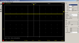
This is what I see coming out of the oscillator circuit:
crystalout.png
Maybe my scope just isn't set up right?
 
Last edited:
well I got my other scope out a portable (hantek 2c42) and it's showing a 16mhz pulse so I guess it was all a red herring. So I'm back to square 1.
 
Now, maybe someone can correct me if I am wrong, but I don't believe the 1571s suffered the same open head issues that the 1541 Neutronics Mitsumi drives had, am I correct in this?

Something to try is maybe check different signals between the two scopes? Maybe something was wrong and the time that you happened to use the Hantek it decided to behave. If your two scope show the same signals on other checks, it may not be a red herring at all.

You mentioned that a cap is a ceramic cap. Is this the C31 you mentioned that was electrolytic?
Yeah, I used both scopes on the oscillator output, the portable one read fine while the one hooked to my PC didn't really register anything (well just that screen shot) I tried playing with the timebase but couldn't really see anything meaningful so I think either that scope doesn't handle 16mhz signals (although it claims to) or the software I'm using doesn't.

C31 is electrolytic and C23 is ceramic. I went ahead and replaced C23 with an electrolytic (this was before I broke out the portable scope) but this had no effect. So it's possible that the original ceramic cap was fine and my cheap-o component tester just didn't do a good job at testing it.

I went ahead and used the portable scope on the pins which I had previously marked as inconsistent with the logic tables in the SAMs manual and the only ones that seemed off still were related to writing data (logic table indicated the pin should be a pulse but was either high or low) but after hooking up the drive to a computer (a VIC-20 I was recently working on so it was near by) and trying to format a disk I did see brief pulses on those lines before the drive gave up about a second later. I think the circuitry is all working as expected, or at least I can't definitively point to anything that seems incorrect.
 
Now, maybe someone can correct me if I am wrong, but I don't believe the 1571s suffered the same open head issues that the 1541 Neutronics Mitsumi drives had, am I correct in this?
Yes, the 1571 drives that have Newtronics drives are also susceptible to open circuit heads. This also includes any Newtronics drives installed in C128DCRs. You can identify these drives as they have a rotary latch lever. Some drives use an Alps mechanism, these have a push down latch, and are not susceptible to open circuit heads.

I had one of these Newtronics drives in my C128DCR with open heads, I fixed it by substituting a completely different mechanism, though be warned its a bit hacky.

https://a4000bear.neocities.org/overclock/1571/1571
 
Back
Top