I have built the dramduino tester and have gone through the memory on my 2nd 5160. I found 3 definitely bad chips. The (maybe) good ones were populated in banks 0 through 2 and the switches set to exclude bank 3. I have the Landmark diagnostic BIOS installed. I am aware that it is not the best of the two possible diagnostic ROMS, but it is here and being used. After startup i had to listen to the beeps for the keyboard and floppy controller errors, so I gave in and plugged them in. My 360k half height is not working, but I was pretty sure it was problematic when I put it in the chain.
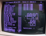
I'm getting a Slow Refresh error at address 2098E Bit 2 and a Parity error at 28000. Everything else except the floppy read test passes. Am I correct in assuming that the "suspected" chip is in bank 2 and would be the 3rd chip? I going to further guess that the parity error is that the bank 2 parity chip doesn't agree with my suspected bad chip.
I know that I could just yank the chip and drop in one of the 6 remaining probably good ones, but I would like to understand why I'm doing something rather than just monkey fisting around with the chip lifter.