• Please review our updated Terms and Rules here

8032 Repair

eight088

Experienced Member
Joined
Oct 31, 2018
Messages
158
Location
Perth, WA Australia
Hi everyone

I've started a repair on a 8032 pet, and so far I've found a bad 4 to 16 decoder. All the /CS lines were active at once, so I replaced the 74154 and now have proper chip selection happening.

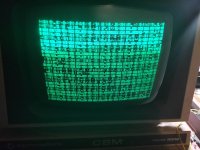
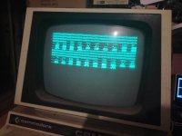
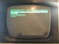
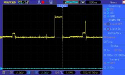
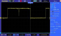
The part that I'm getting stuck at is getting a display. One thing I did notice was when the original edit rom was in, there was vertical collapse on the screen, but the line was bouncing round a bit... As soon as I noticed this, I switched it off. I checked the horizontal and vertical drive signals they were well out of spec. I put in the pettest rom, and these signals now come good - Horizontal 20khz, and vertical 60hz. I could also see the video pin pulsing so I knew data should be getting displayed on the screen. Unfortunately, I have nothing! I've probed a few places on the vdu pcb, but I haven't found anything wrong just yet.

So what I was wondering, is if the edit rom needs to be modified to support the Australian pet I'm working on? I read the documentation and it says it only needs to be modified for 40 column pets. I did notice though in the table for the crtc init, there are different values for pet/cbm 60 or 50hz, and pal 50hz. Should I modify the rom for pal 50hz? (or use pet/cbm 50hz?)

Cheers
 
I have a 50Hz CBM 8032 and could use the Pettester without modifications. What's the CPU doing? Did you do the usual maintenance (check all voltages / ripple, deoxidise sockets, connectors and reseat ICs)?
 
I have a 50Hz CBM 8032 and could use the Pettester without modifications. What's the CPU doing? Did you do the usual maintenance (check all voltages / ripple, deoxidise sockets, connectors and reseat ICs)?
That would be great! I've done all the usual maintenance, and as far as I can tell the CPU is executing instructions as the SYNC signal is pulsing nicely. I'm getting nothing on the screen, so wanted to rule out that the pettester rom is fine and doesn't require changes, or if I need to look further for a problem on the VDU.

Cheers
 
I've checked to see if the pettester is being selected and seems like it is functioning as expected. There is also good looking activity all on the data bus' and address bus'. I'm wondering if a 3032 9" monitor will (should) work? Maybe I can use that to diagnose further...

Cheers
 
Could you verify the waveforms in the VDU circuit? Unfortunately work is in the way else I would have popped open my PET and find a suitable test point.

Another monitor should work if the drive and video signals are handled the same way as in the original VDU. I think on some PETs it's inverted, but I'm not sure... I only know what I learned from here. Someone will eventually show up and give better advice :)
 
Thanks for the help so far powerlot. I have checked numerous test points on the VDU and so far, they are all looking good. I think I'll need to go back and double check.

Cheers :)
 
Well, I feel like an idiot... I turned both brightness and sub brightness right up, and now I get an image! Completely displays the wrong image, so I will investigate this further and hopefully come up with something :)
 
Well, I've made some good progress over the last couple of hours... With the monitor now displaying a picture, the first character test of pet rom was all screwed up, with every second character flickering. I worked this out to be a bad odd screen memory chip at C6, so replaced that and then got a screen with no flickering but still incorrect characters. This ended up being the second odd memory chip at C7, and with that replaced the pet whisked through the character test so quick that I couldn't see it and was at the first memory test screen. It gave me a bunch of g's and b's, so I'll go back to the most excellent write up by daver2 and see what I can work out from there!

I really get a buzz when making some progress! :)
 

Attachments

  • C6 replaced.jpg
    C6 replaced.jpg
    289.5 KB · Views: 12
  • C7 replaced.jpg
    C7 replaced.jpg
    198.8 KB · Views: 12
Nice! I also had a defective screen memory chip on mine, you figured it out pretty quick.

Now, probably one of the page 0/1 RAM ICs are malfunctioning (or logic chip around it). You can try to figure it out from the manual which one it is... I didn't have a single failed RAM IC, mine are all from Toshiba if it means anything.
 
I didn't have a single failed RAM IC, mine are all from Toshiba if it means anything.


Yes, that does in fact mean something, a lot really.

Japanese IC' s are extremely reliable.

I have mentioned this before, if you are sourcing IC's for vintage computers, be they memory IC's, or 74 series logic IC's, go for Japanese, Toshiba, Mitsubishi, Fujitsu etc.

Part of this comes from the Japanese quest for excellence in electronics, but it is more, they never give up, practically never sleep, until what they make is perfect. The pride in their work is admirable. And not lost on me.

I admire their attitude to solve problems in mechanical and electronics Engineering. They are not happy to release parts from their production lines unless they are 100% happy they are perfect.

You might ask yourself: "Why are Toyotas the most reliable cars on the planet". These things never happen by accident.
 
I just want to check on my understanding of the memory test I'm seeing...

Are the first 4 g's page 0, and the first 4 b's page 1? (in the image on post 10). I think I've worked out that bit 6 (counting the first bit as 0) is stuck. The way I worked that out is its reading (in binary) -

  • 0100 0000 (@) instead of 0000 0000
  • 0100 0001 (a) instead of 0000 0001
  • 0100 0010 (b) instead of 0000 0010
  • 0100 0011 (c) instead of 0000 0011

Am I going about this the right way, or am looking at it wrong?

Cheers
 
I just want to check on my understanding of the memory test I'm seeing...

Are the first 4 g's page 0, and the first 4 b's page 1?
No, the first 256 characters are page 0 and the next 256 are page 1. It looks to me like both pages have the same problem. It may be an addressing issue with four good bytes followed by four bad bytes. I would take a look at address bit BA2 to the 244 buffer (UE9 pin6) of the RAM chips. It may be stuck Low. If it is toggling OK then perhaps the UE9 LS 244 buffer is bad. Check its output on pin 14, but it will be a multiplexed signal and may be hard to determine. See schematic of RAM on page 5 http://www.zimmers.net/anonftp/pub/cbm/schematics/computers/pet/univ2/8032087-05.gif

EDIT: It could also be the controls to the buffer that are bad. Daver2 may suggest going to the NOP Generator if the problem turns out to be tricky.

Thanks Dave, glad I checked here first before proceeding!

I've already testing all the address lines with the NOP generator, but it might be a good idea to double check the results. I'm at work atm, but I'll dig back into it this evening.

Cheers
 
A while back I made a testing system for analyzing the DRAM in my dynamic PET. I put about 20 scope recordings in this document on the circuitry that supports the DRAM. The idea was to be able to check the DRAM no matter how defective the DRAM itself is, or how defective the DRAM support circuitry is, and also if the BASIC OS was not running due to defects in the lower DRAM pages. If the BASIC is running, the Hardware adapter described there is not required and just the ROM programs are helpful.

Although my PET model is not the same as your PET, the principles and DRAM control signals are the same. You can also use the programs I put in a ROM to check the DRAM memory, so it may have some use. There are also details on the types of faults that occur with the DRAM IC's and the way these appear on DRAM testing and the ways to conclude which IC's are defective:

 
Last edited:
I have another update -

I checked UE9 and that seemed to have good inputs and outputs. I ruled this out as possibly being bad and turned my attention back to the g's and b's I was getting on the screen (post 10). Realising my mistake about page 0 / page 1, I worked out what was being read back, compared to what was being written to memory and data bit 2 looked sus. I scoped pin 2 on UA14 and 15, and the waveform looked like there was a moment where the chip was trying to drive the bus high. Not sure whether it would be UA14 or UA15, I piggy backed them with spares that I had. I know this isn't a true and proven method, but it has worked for me in the past so thought I'd give it a go. I also knew this could send me down a rabbit hole...

So I piggy backed UA14, and no change. Tried UA15 and it proceeded to the next step in the pettester! With excitement I quickly removed UA15, soldered in a socket and put the new replacement in and it sprung into life! It has now passed a couple of memory checks so far, but I'll let it run for a while still.

So all in all, I had a bad 74154 decoder at UE12 preventing proper chip selection, two bad screen memory chips at UC6 and UC7, and one bad memory chip at UA15.

I do think the CRT is very worn though, because I have to have the sub brightness and brightness all the way up to get an image. Maybe I can find an amber tube to replace it haha

Thanks for your help everyone :)
 

Attachments

  • 315521512_507612944733228_8367107515554429068_n.jpg
    315521512_507612944733228_8367107515554429068_n.jpg
    170.4 KB · Views: 11
  • bad UA15.jpg
    bad UA15.jpg
    119.4 KB · Views: 11
  • UA15 replaced.jpg
    UA15 replaced.jpg
    120.5 KB · Views: 11
I do think the CRT is very worn though, because I have to have the sub brightness and brightness all the way up to get an image. Maybe I can find an amber tube to replace it haha

Thanks for your help everyone :)

Possibly not the CRT gun is at fault. As a CRT ages, the main thing that goes off is the focus. If the CRT beam is still focused reasonably well, it might be ok. And the problem be in the CRT's support circuitry. The CRT's beam focus looks reasonably sharp on the photo you posted. The max beam current (and brightness) that a CRT can deliver occurs when its grid to cathode voltage approaches zero. Pushing the grid more positive than the cathode simply de-focuses the beam without any significant increase in beam current (brightness).
 
Last edited:
Well done.

At the screen photographed in post #17 - you can test out the keyboard (before the countdown gets down to 0 at any rate). Each key press should result in one of the bits changing state from 0 to 1 on the line marked 'kbd'

Also, double check the ROM checksums against those in my PETTESTER manual.

After the countdown gets to 0 - the full memory test starts. Get about 20 full passes of the memory test to be sure. Also note that the PETTESTER has detected ALL of the memory within the machine (e.g. displays 32K if you have 32K fitted)!

Dave
 
Back
Top