• Please review our updated Terms and Rules here

Altair 8800

falter

Veteran Member
Joined
Jan 22, 2011
Messages
6,586
Location
Vancouver, BC
Hi!

I picked up this 'hodge-podge' Altair 8800 over Xmas. A while back I had gotten a bunch of Altair Rev 0 parts, including CPU and RAM cards, as well as the top and bottom of the case. Someone was kind enough to offer me the internal chassis from an 8800b turnkey, and my intent was to build the thing up from there. However, I eventually got discouraged. The front dress panel for an 8800 is almost unobtanium, and one that came up about a year ago went for over $600. The actual 4 slot Altair bus seems to come up infrequently, and the power supply almost never. Since the front panel board I had had no switches or LEDs, finding period correct parts was going to be almost impossible.

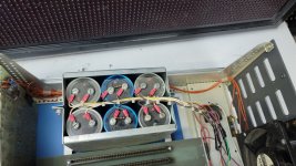
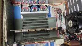
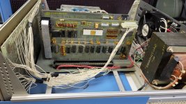
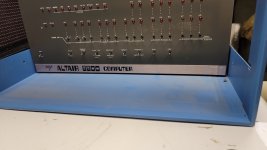
So then this other Altair comes up for sale, and it's a lot cheaper than usual because it has an aftermarket S100 plate, and an 'upgraded' power supply, the dress panel is missing its badge and so on. I got it for $2k, and was happy with that because it at least gives me the chance to actually use thing. Yeah, it has some issues, but it's not $6k, so there's that. It had a Rev 0 CPU and 1K RAM card, and at least according to my records that kind of checked as I found at least 4 machines in the early serial 223xxx range like this one that had Rev 0 cards like this one. I decided to sell my other Altair parts, keeping only the outer cover, and my thinking is I'll build the 8800b turnkey chassis into an 8800b turnkey again one day. This machine didn't have the metal Altair badge, but I had an NOS one so I used that.

However, after the auction, I asked the seller for some background info as he was the original owner, and he tells me that this machine was actually a Rev 1 originally, and for some reason he had taken out the Rev 1 CPU card, and subbed in a Rev 0 he had from another prior machine. He told me he planned to sell the Rev 1 card separately later on. I thought that was odd.

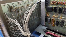
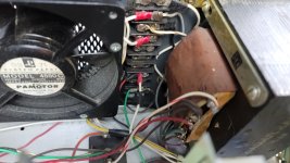
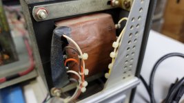
The seller tells me the power supply puts out +10V, so it really generates some heat on the voltage regulator for the CPU card, so he's got a big long heatsink on it. Doesn't have one for the VR on the memory card.

In pics, he fired up the machine with the cards in it. So if that could have caused any damage it's already done, but he says he ran it like that for years. Anyway, I did my due diligence and checked out the voltages on pins 1 and 2 and 51 and 52, and sure enough we're getting +10V on 1 and 51, as well as 19.5 on pin 2 and -19.5 on pin 52.

My question is, can it actually run like this safely? I do intend to look for an original 8800 PSU, but I think it'll be a long time before I see one. Would love to use it in the meantime. I'm sure the +5V regulators can handle an extra +2V incoming, but I'm not sure how things are regulated for what's supposed to be +16 and -16v.

20230120_172713_resized_1.jpg20230120_172727_resized_1.jpg
 

Attachments

  • 20230120_172723_resized_1.jpg
    20230120_172723_resized_1.jpg
    779.9 KB · Views: 18
  • 20230120_172715_resized_1.jpg
    20230120_172715_resized_1.jpg
    726.9 KB · Views: 17
  • 20230120_172713_resized_1.jpg
    20230120_172713_resized_1.jpg
    900 KB · Views: 15
  • 20230120_172706_resized_1.jpg
    20230120_172706_resized_1.jpg
    659 KB · Views: 17
  • 20230120_172700_resized_1.jpg
    20230120_172700_resized_1.jpg
    552.8 KB · Views: 20
  • 20230120_172655_resized_1.jpg
    20230120_172655_resized_1.jpg
    863.2 KB · Views: 24
  • 20230120_172651_resized_1.jpg
    20230120_172651_resized_1.jpg
    489.8 KB · Views: 24
  • 20230119_210107_resized_1.jpg
    20230119_210107_resized_1.jpg
    539.3 KB · Views: 20
If it was me, convert to modern power supply with proper known good voltages and call it done. its inside the case nobody will see it, and you want to actually use the machine why deal with 45+ years of something else failing and blowing all the chips, works great for a week then you power it off for a while turn it back on and BOOM major damage.

if its a museum piece that is another story.
 
I lost the front panel badge to my Rev 0 decades ago. The stickum on the originals tended to dry out. The last I remember seeing it was on the kitchen counter 2 houses ago. No, I haven't powered mine up in over 30 years. I doubt that the PSU is any good.
 
Later S100 systems had high voltages like you’re seeing because by the time you installed a bunch of cards, the voltages dropped due to the higher current load.

The 8800b transformer had three lugs to choose from for the 8v supply that were at slightly different voltages. You used the lug that gave the output voltage you wanted based on the current draw of your system.

For the original 8800, a zener regulator became standard to reduce the 8v supply (which was often 10v or more in a lightly loaded system) to about 9v. See the upper corner of this schematic:


You can see the parts installed to the left of the power supply board in this picture:


Ironically, as more and more boards became available and users added ore boards to their systems, they had to remove this regulator because voltage was then drooping too much.

Mike
 
I lost the front panel badge to my Rev 0 decades ago. The stickum on the originals tended to dry out. The last I remember seeing it was on the kitchen counter 2 houses ago. No, I haven't powered mine up in over 30 years. I doubt that the PSU is any good.
I have a few reproduction name plates for the original Altair that look really close to the original if you want one.

Mike
 
If it was me, convert to modern power supply with proper known good voltages and call it done. its inside the case nobody will see it, and you want to actually use the machine why deal with 45+ years of something else failing and blowing all the chips, works great for a week then you power it off for a while turn it back on and BOOM major damage.

if its a museum piece that is another story.
Yeah.. I could do that I guess.
 
Thank you. So you guys think I'm probably alright to run it for short periods as-is? The other guy obviously was.

One other q - has anyone ever written a book or anything that details Altair production.. sort of a collector's guide? With the Apple II we know what serials roughly Revisions and components changed. I'm wondering if we have something like that knowledge for Altair. I wanted to know where Rev 1 began for example and if it was consistent or if different revisions mixed for a while. My own info is all over the place.. my sample size is too small to say anything with authority.
 
I have a few reproduction name plates for the original Altair that look really close to the original if you want one.

Thanks for the offer, Mike--but then I'd have to refurb the thing so it works. At any rate, I'll think about it. When I think of the Altair box, all that comes to mind is lots of cheap white wire.
 
Thanks for the offer, Mike--but then I'd have to refurb the thing so it works. At any rate, I'll think about it. When I think of the Altair box, all that comes to mind is lots of cheap white wire.
I have a sealed roll of MITS cheap white wire from the previous kit I had if you want to reminisce without having to open the box... 😉
 

Attachments

  • 20230121_104234.jpg
    20230121_104234.jpg
    763 KB · Views: 12
Forget that--that stuff was what, 5 or 7 strand--it'd break if you wiggled the wire more than a few times.
Yup. During transit the CPU card got loose inside, I'm surprised only two wires were broken. It would have been nice if they'd supplied some additional colors... I go crosseyed trying to follow them. But I guess they were economizing to keep the sticker price down.
 
I broke out the manual and started reading today. Interestingly it is different than the previous manual I had. I'm suspecting this is a later manual and the other I had was a first revision. The one I now have has the MITS logo on the front, the other one does not. The MITS logo one has a whole page of corrections that the other one I had didn't. The price list in the MITS one is dated March 1975, most of the price lists in the other manual are dated same, but one for the chassis is dated Feb 1975.

The manual says I actually should be expecting +10V on Pins 1 and 51, +20V on pin 2 and -18V on Pin 52 with the system unloaded, and so far that checks out.

I've now stepped my way through the checkout procedure for the CPU board installed by itself, and so far it's doing exactly what the manual expects - reset seems to work, address lights light up one by one as you examine them. I'm doing sort power ups and use - I don't yet trust this thing and keep cringing expecting something to blow up.

This is so cool for me. I've never seen a real, complete Altair up close before. Only in videos. Yeah, this one's not exactly stock specs, but it's providing the same look and feel and it's not costing me $6k.

One other thing I'm wondering about.. the fan says 220-230V.. not 110-120? It seems to start up with a slight clunk as its getting going..

I wonder if there are ways to restore the missing front panel silkscreen without redoing the whole thing? It doesn't bother me that much as is though.
 

Attachments

  • altairdocearlier.jpg
    altairdocearlier.jpg
    78.3 KB · Views: 4
  • altairdoclater.jpg
    altairdoclater.jpg
    162.7 KB · Views: 4
My 8800 never came with a fan. Really, if all you're using is 4 boards, a fan shouldn't be necessary.
A 220V fan will work on 120V, but spin more slowly--and with less noise.
 
My 8800 never came with a fan. Really, if all you're using is 4 boards, a fan shouldn't be necessary.
A 220V fan will work on 120V, but spin more slowly--and with less noise.
Yeah the only thing I might have wanted to do with mine is connect and use with a Teletype. So more RAM and a serial board (I think that's what's required). But as I understand it the MITS board for that is super rare.

I'm curious.. how early in production was yours? Was it a kit or assembled unit?
 
It was a kit--I spent an entire weekend on coffee putting it together. It was the "special deal" offered in Popular Electronics that sold the box, the CPU, SIO, and 2 4K DRAM boards for the measly sum of $1,000. Oh, how I hated those DRAM boards! Eventually picked up a couple of 8K (SSM I think) SRAM boards using 91L02s--64 of them.
 
Interesting. So yours must have been a little later if it was coming with 4k boards.

I'm trying to figure out how to set the 1k board jumpers. The manual doesn't explain beyond telling you to do it one way (under the assumption you only have the one board) and says details to come. I have a 4k dram board but I've heard horror stories like yours... heh
 
The 4K DRAM boards had shunt resistors across the voltage regulators and some interesting patch wires. 22pin 4Kx1 DRAMs that would drop bits every time you hit the reset switch.
Probably late 1975; the 4K board was advertised in the May 1975 PE ads.
 
Nice buy.

I think I can answer your 1K RAM question.

On the schematic you will see a large NAND gate. In order for the RAM board to be selected, all of the NAND gate inputs need to be a '1'.

Your first 1K RAM board will be addressed as 000000, the second as 000001, the third as 000010 and so forth. These are in the order of address lines A15, A14, A13, A12, A11 and A10.

For every address line that is a '1', wire the corresponding input of the NAND gate directly to the S-100 address bus pad. For every address line that is a '0', wire the corresponding input of the NAND gate via the inverter gate that is connected to the S-100 address bus pad.

Hope this is clear?

Dave
 
The other way of doing it as follows. This method is helpful if you require a lot of memory boards to be contiguous from address 0000, but the odd one at a strange high address.

Identify the four-digit hexadecimal address of the desired base address for each of the memory cards. Discard the lower two (2) digits of this address. Convert the higher two (2) digits into binary (giving 8 bits in total). The lowest (least significant) two bits should be 00. Discard the lowest two (2) least significant 00 bits. What you have remaining is the A15 through A10 settings required above. By means of an example:

Board #1 Base address 0000 = 000000.
Board #2 Base address 0400 = 000001.
Board #3 Base address 0800 = 000010.
Board #4 Base address 0C00 = 000011.
Board #5 Base address A000 = 101000.

Convert the six binary bits you have remaining into the sequence of direct-wiring the NAND gate input to the S-100 address pad for a binary '1' or going through the inverter for a binary '0'.

Incidentally, this technique also works for larger memory boards using the same address decoding circuitry, but you discard proportionally more of the least significant address bits. For example, for a 4K memory board, you only require the most significant four (4) bits of the base address.

It also works for systems containing (for example) mixtures of 1K and 4K memory boards.

Dave
 
Last edited:
Back
Top