• Please review our updated Terms and Rules here

Amstrad PC14HRCD monitor, is it repairable?

VintageVic

Experienced Member
Joined
Dec 9, 2019
Messages
340
Location
Finland
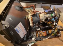
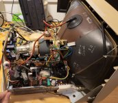
I have started my attempt to repair this Amstrad VGA monitor, capable of 640x480 resolution. Advices and suggestions
are most welcome! This unit came with Amstrad 2286 that had been stored in cold storage for years.

If anyone is inspired to open their own monitor by this attempt, remember to take EXTREME caution and discharge
that potential 30kV residual charge on your crt monitor any time you work on it. Not that I'm recommending anyone to
take such a project, any such attempt is on your own risk.

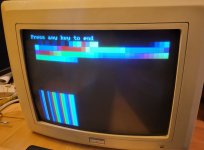
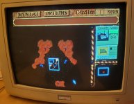
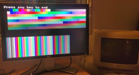
But to this case. I have tried this on for a few months ago and already knew that it seems to have red color
available, but no green or blue. I made simple quick basic program to display screen 13 and 256 different colors
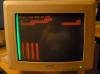
on the screen. On a working monitor it looks like pic 1.jpg, but this Amstrad monitor looks like pic 2.jpg.
Don't mind the blurriness, it came from bad image. Image is sharp, but really only red is available on the screen.

Except for a small green part on the left of the monitor. It seems like the green has somehow collapsed on the left
side. and blue is completely missing unfortunately. At least the red gives hope that perhaps the monitor is repairable.

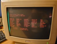
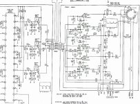
I have found the schematics and parts list for this monitor. They are slightly imperfect scan quality, but waaay better,
than no schematics at all! It makes troubleshooting worthwhile.

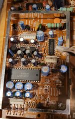
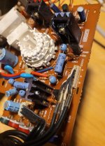
I have done some initial testings and tried to locate the video part of the board (6.jpg). Already checked that
the vga cable RGB signals have continuity.

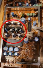
The big IC in pic 6.jpg is: M51387P (3-channel video amp, for Hi-res monitors).
I measured three VCC legs of this chip having 11.98V input voltage that looks like good to me.
Voltages from three other legs:
leg 29 (red out) 3,19 V
leg 25 (green out) 0,89 V
leg 21 (blue out) 3,09 V

I'm no expert here, but something seems off on the green color circuitry, if not exactly on this IC itself.
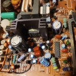
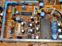
Other possible 'might be' candidates (I'm just guessing here) could be IC4001: LA7851 (CRT display syncronization deflection circuit)
or perhaps IC4002: UPC1378H (Vertical deflection circuit).

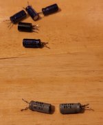
I did measure good number of transistors for shorts, but found no short on them.

If the symptoms described here rings a bell or raises ideas, let me know what you think I should check next.
In the meantime, I'll probably be trying to improve the quality of the schematics and checking simple components such as
diodes and resistors to rule them out on the green color circuitry.
 

Attachments

  • 1.jpg
    1.jpg
    168.9 KB · Views: 23
  • 2.jpg
    2.jpg
    80.9 KB · Views: 20
  • 3.jpg
    3.jpg
    144.1 KB · Views: 22
  • 4.jpg
    4.jpg
    182.1 KB · Views: 18
  • 5.jpg
    5.jpg
    191.5 KB · Views: 18
  • 6.jpg
    6.jpg
    194.2 KB · Views: 24
If anyone is inspired to open their own monitor by this attempt, remember to take EXTREME caution and discharge
that potential 30kV residual charge on your crt monitor any time you work on it.


Not true. No need for the EXTREME hyperbole.

If you don't go under the CRT's anode cap there is absolutely no need to discharge the CRT for general work & most repairs. Most repairs do not require that you go under there, unless you want to remove the CRT itself or the LOPT or go under there to measure the EHT voltage with a high voltage probe. The charge remains "safely" inside the CRT if you don't go under the anode cap or remove it. Don't believe everything you see on youtube videos about the requirements to discharge the CRT for general repairs "any time you work on it" that sort of misinformation abounds.

But, rather than being worried about the charge stored in the CRT, that you could contact if you went under that anode cap (the energy stored there is less than a Farmer's electric fence that won't kill you) you should be more worried about the other voltages that exist in the VDU when it is running. These are often as high as 400V and can source more than 10 to 30mA in some cases. So with those, if you are working on the VDU, when it is powered and running, you need to observe suitable precautions, just like you should if you were working on tube amplifier gear with similar voltage sources. But if you are doing tests on components in the VDU with the power off, there is no problem, if you let it rest for an hour or two after turn-off, so that the power supply electrolytics have discharged.

Also the question "Is it repairable" of course it is. Unless the CRT itself is damaged, because CRT's are a non renewable resource now.
 
Last edited:
But if you are doing tests on components in the VDU with the power off, there is no problem, if you let it rest for an hour or two after turn-off, so that the power supply electrolytics have discharged.
Worth noting the electrolytics in some monitors / equipment don't always discharge even after weeks / months of not being powered up, I learnt this lesson a long time ago, I was removing the main board from an IBM 5153 monitor, I had both hands inside removing the main board and got zapped, My left arm hurt for a week after, I don't know what i touched but i clearly wasn't paying attention to what i was doing and it hurt. This monitor had not been powered for over a month and i thought it would be discharged and quite safe but was i wrong.
 
Yes,

I may have been inaccurate there, but the point was do not be careless. Electrical charges can be fatal with these monitors.

Anyway. I've been studying the schematics and improving their quality. I have also ordered a few IC's and transistors from ebay. I expect
those to arrive from several weeks to a few months. Spent around 50 € on these so far and I'll probably order several more transistors too.
Economically this makes no sense, that thing has no resale value, but I guess everyone wastes their money one way or another.
 
Worth noting the electrolytics in some monitors / equipment don't always discharge even after weeks / months of not being powered up, I learnt this lesson a long time ago, I was removing the main board from an IBM 5153 monitor, I had both hands inside removing the main board and got zapped, My left arm hurt for a week after, I don't know what i touched but i clearly wasn't paying attention to what i was doing and it hurt. This monitor had not been powered for over a month and i thought it would be discharged and quite safe but was i wrong.

It is difficult to understand how that happened as it appears to violate the rules of Physics. Perhaps somebody powered it up just before you went in it.

Most of the electrolytic caps in VDUs in the power supply, on the line side, have bleeder resistors across them, but sometimes they don't. The others on the secondary side of the PSU power circuits that draw current and discharge the caps in a fairly short period after turn off.

If you consider a large electrolytic capacitor on the line power side of the supply, say 500uF discharging into a 220k bleeder resistor the time constant is 110 seconds. After 5 time constants (0.63^5 = 0.1), then 90% of the charge is depleted from the capacitor, so 550 seconds or 9 minutes to deplete the charge (and voltage) down to 10% in that example.

Sometimes these bleeder resistors go open circuit though, as resistors with high voltage applied can do. Or the manufacturers didn't use them. Electrolytic caps though, have an intrinsic leakage current. Very seldom would that be equivalent to a resistance of higher than 10 meg Ohms. In that case the time constant could be 5000 seconds, and nearly fully charge depleted at 25000 seconds, 416 minutes or 6.94 hours. Or say 14 Hrs if the electrolytic caps leakage was an astonishingly low 20 Meg Ohms.

Looking at the 5153's schematic, they did not use bleeder resistors across the two 120uF electrolytic caps on the line side of the psu, but these would be fully self discharged in a day for sure. To make sure I'm not putting you wrong here, I just performed a leakage resistance test on a new 120uF 400V electrolytic cap, it is just under 2 Meg Ohms, so they (the two of them in the 5153 in parallel) will be near fully charge depleted (down to 10% terminal voltage) about 20 minutes after turn off. ( 240uF x 1 meg Ohms x 5 = 1200 seconds =20 minutes).

Generally a non electrolytic or film capacitor can hold charge for months, but to hold that its terminals have to be completely isolated from anything else.

There was once a system of an analog memory. It was used in vintage color video cameras to remember a DC voltage value. It consisted of a film capacitor on the gate of an insulated gate mosfet, wired as a source follower. A reed relay impressed the voltage on the capacitor. Then the relay would open and that voltage stayed there on the gate & capacitor for weeks, not months before the tiny gate leakage current, slowly discharged it. It was a good trick to make a simple analog memory though.
 
Last edited:
It is difficult to understand how that happened as it appears to violate the rules of Physics. Perhaps somebody powered it up just before you went in it.
No one powered it up as i'm the only one who had access to it, Like i said i don't know what i touched but it bloody hurt, I've learnt to treat monitor's / Electronics with caution, Recently powered or not...
 
No one powered it up as i'm the only one who had access to it, Like i said i don't know what i touched but it bloody hurt, I've learnt to treat monitor's / Electronics with caution, Recently powered or not..

It does always pay to treat any apparatus with caution, especially if it contains a voltage source of over 70V and that source can provide over about 15 to 30mA of current.

It is about at these levels that the voltage source becomes hazardous.

On the other had, if there is some stored charge, up to a few Joules from the energy perspective, it is not too worrying, as a one off of hit.

Car spark plug and lawnmower plugs have about 15 to 40mJ per pulse.. The Farmeres electric fence up to 5J per pulse or over.

Apart from energy considerations and risks from those, part of the issue is the way people react after receiving the high voltage charge.

If you are sort of used to it like I am, you don't over react and regard it is an inconvenience. On the other hand, you can react by throwing tools and a lot of four letter expletives.
 
Last edited:
Some of the IC's that I've ordered have started to arrive. I've replaced what I have received.
There is no change for better and luckily not for the worse either.

Replaced IC's so far are IC4001 (LA7851) and IC4002 (UPC1378) that are shown on the attached image.
Those are still the originals. Also IC101 (M51387P).

I also realized that I could try a sort of substitution attempt on items that are on working red rail
and swap them to the green rail. I have done a swap to Q801 (2SC3790) to Q803 (and vice versa)
and also swapped Q101 and Q102 (2SD1207T transistor).

Since none of the changes actually changed anything, I'm assuming all of these transistors ok.
The RED color still works the same, but green is tilted or stuck at the left side of the screen.

I was putting a lot of hope that the fault would be at the IC's or transistors of the green and blue rail,
but now it seems it might not be the case. I haven't changed any of the electrolytic caps, or any of the other
caps either for that matter.

Does replacing the elcaps get a vote, or is there perhaps any smarter move to try first? I'd have to order them
first too. Well, I will sleep over it and think about the next move.

Oh, I also measured voltages of some of the transistors here.

Q / E / B / C (volts)
Q802 / 3,6 / 4,1 / 11,3
Q804 / 4,2 / 4,7 / 11,3
Q806 / 3,5 / 3,9 / 11,3

Q801 / 11,4 / 11,9 / 123
Q803 / 11,3 / 11,9 / 131
Q805 / 11,3 / 11,9 / 138,6

It won't tell me much, but at least the transistors are not shorted.
I can't see very clearly from the schematics the correct voltages for red, green and blue outputs.
But if I read it right, Red output should be 109V, Green output 113V and the Blue output about 118V.
If this is correct, the measured values from collectors Q801, Q803 and Q805 are somewhat too high.

Are they way off, sufficient to cause experienced symptoms (Green to the left of the screen and blue completely
missing) I don't know, but it could, right?
 

Attachments

  • IC.jpg
    IC.jpg
    216.6 KB · Views: 8
  • VIDEO_pcb_partial.jpg
    VIDEO_pcb_partial.jpg
    207.6 KB · Views: 8
The 3 colors all share the power voltages and so I'll guess that there nothing wrong with power. In fact the three colors have nearly the same circuits and so you could try swapping the Red output to the green (or blue) to see if the CRT itself is the issue. If "red" drives the other colors then you have some more troubleshooting to do with the missing colors. If the CRT doesn't display the green or blue then the CRT tube is shot.
 
That might be clever to check out!

I could easily swap R and G wire here, but that would be taking a wire from between Red Out (Q101) and Red drive (Q802)
and putting it between Q102 and Q804.

Making a swap after R827 and R828 is a bit more fiddly, but I figured it is also doable. I don't know if the wire swap proves
anything though, so I could try this fiddly swap next.

I have now also replaced green drive Q804 and blue drive Q806 since I got those transistors from mail. And that did not
change how the monitor operates at all.
 

Attachments

  • swap.jpg
    swap.jpg
    243.1 KB · Views: 2
The fact that the image looks well focused, and there's a bright green band on the left tells me that the CRT is probably fine. I would start with checking for bad capacitors, particularly smaller ones in hot areas. The caps I have circled here should be tested, or replaced since they're small, and the board under them looks discolored from heat.
 

Attachments

  • 6.jpg
    6.jpg
    154.5 KB · Views: 7
What do you know, it does look like that area has been hot. I will start by listing caps that I need
to order. Some I might have at home. I will replace those caps when I got spares.

One more suspect caps perhaps, the C4072, shown here on the left. According to the parts list it is polypropylene capacitor,
0.068 uF in value. Looks like milk coffee color, I wonder if that is normal? In the PC power supply had similar
shaped caps, but they were silvery in color. I wonder if they have made these in beige or has it changed color from
silver (while being corrupted).

I haven't found it on the schematics yet, since it's a bit lowres and blurred. I will try to find out what it is related with.
 

Attachments

  • caps.jpg
    caps.jpg
    189.7 KB · Views: 10
Could be darkened from heat-exposure. Did that enclosing frame have a lid that would trap heat or is it open by default?
 
C4072 looks fine. That type of cap rarely fails, and has no liquid to dry out from heat. They come in all colors.

The 3 caps nearest those 3 transistors would be my prime suspects. It looks like one has already been replaced since one is blue, and the others are grey.
 
It does look like the three transistors were the source of the heat which darkened the pcb, so the capacitors close to them have likely dried out, they could be checked in circuit with an ESR meter. When caps dry out not only do they lose uF capacity, but the ESR goes up significantly.
 
Thank you for your comments!

@GeartTechWolf, yes; the frame has a lid. I have removed it to have access to the components.
@andy, okay, I don't worry about that C4072 too much.

I browsed my stock yesterday and listed the caps what I have at hand.
C127, C129 and C131 are the ones near the hot going transistors (Q101-103) and
they are valued 22uF/25V. These I have at stock and I will be replacing them tonight.

I also have 2,2uF/50V caps, so I can replace C104-106 near the IC 101 (Video amplifier) as well.
This gives me a good start. If replacing these won't make a difference, I will need to list
the rest of the electrolytic caps for ordering.

Edit:
Actually, C126, C128, C130 are very next to the Q101-103. They are valued 47uF/25V.
I have one of these at stock and one 47uF/200V. I think these have the same capacitance
so I could also use that 47uF/200V as a replacement here right?
 
Well, well.

A gathered spares that I had when I got home and warmed up the soldering tool
Replaced all of these while I got to work:

C105, C106 (2.2uf/50V), C128, C130 (47uF/50 that I found), C129, C131 (22uF/25V)
and also Q103 for the blue rail.

Fingers crossed I started the pc and then the monitor and waited for seconds to see anything.
aaand... while not perfect, a whole lot better! Wow!

It's not quite there yet, but I'm glad it took a big step forward. "2.jpg" is showing there is definitely
some colors still missing, although I can see that green is no longer tilted to the left and blue has also appeared!
The image is still a bit dim, perhaps especially the red. Larry and Jones in the fast lane do not actually look
so bright as they do on the picture here, samsung camera brightens the image up while naked eye sees it
dimmer. That dune 2 image shows better that the image is too dim.

Perhaps dune has more red in the picture, since the game is in more brown color environment?
Or maybe all of the colors are still a bit dim.

Anyway, I have not yet replaced those same caps on the red line what I did for green and blue. I might as well
try to replace them next since I still have a few suitable spares.

I'm not sure if my cheapo chinese ESR meter is showing right while it measures about 95pF for them old gray'ish caps (47uF/25V).
They have actually been blue originally. They have darkened so much that the image looks like gray. They've obviously gotten heat and tand.

If the monitor wont become fine with replacing these same caps on the red line, there are still several small electrolytic
capacitors on the crt board that I could replace. I don't think I got correct values at stock, so I'll have to order them first.

BIG thanks for your suggestions already here! I would not have started from those caps near heated pcb area. I didn't
even notice that dark brown area there before it was mentioned. Power of many eyes and second opinions!!

And merry christmas for all :)
 

Attachments

  • 1.jpg
    1.jpg
    96.4 KB · Views: 11
  • 2.jpg
    2.jpg
    150.9 KB · Views: 13
  • 3.jpg
    3.jpg
    192.4 KB · Views: 13
  • 4.jpg
    4.jpg
    169.8 KB · Views: 13
  • 5.jpg
    5.jpg
    137.2 KB · Views: 12
  • 6.jpg
    6.jpg
    172.6 KB · Views: 11
Looking at picture 2.jpg in my previous post, it seems there are bright colors
of all red, green and blue missing. They are not just darker, but completely missing.

I went on replacing caps. C106, 126 and 127 are now replace.
Also C118-120 (100uF/25), C108-110 and C121-122 (330uF/16V) and also C801 (0.1uF/30V).

These did not bring further improvement and I'm now out of suitable spares. I guess
I will go on listing electrolytic caps that are not yet replaced and order them. There are plenty of
capacitors to replace, if I were to change them all.
 
Back
Top