• Please review our updated Terms and Rules here

Another IBM 5151 monitor troubleshooting thread

VeryVon

Miner 2049'er
Staff member
Joined
Oct 21, 2021
Messages
328
Location
Land of the Cheesesteak
Hello, I have a 5151 here with no picture, no raster. Was working just fine before, but now nothing. I’m following the SAMS troubleshooting guide, and I do have it connected to a known working 5160 video signal while testing.

Initially the fuse was blown, so I replaced that and the rectifier diodes D601-D604 for good measure even though they seemed ok.

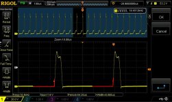
I’m working through the power supply, and it all checks out until I get to the output of TR24 (see picture below) which should be 14.9V, but is more like 5V. Also the voltages coming from the T502 flyback transformer aren’t being developed. Heater is not glowing.

I’ve already replaced TR24, IC601 and a couple of capacitors on the board. Overall it's in good shape and I’ve visually inspected and sanity checked the components I can. My gut feeling is there is something hung up downstream of TR24 but I can’t find any obvious shorted or open components. Could use some help on this.

5151 Sams Schematic.PNG
1675006902215.png
 
Perhaps disconnect the output of the power section from the rest of the circuit (breaking the connection between IC601 pin 3/C601/TR24 and the rest of the board. If the voltage pops up to 15v, then you know for sure it is downstream. Test the 5.1v zener as well. You should be able to isolate by breaking it into sections.
 
Yes, highly likely the output of the voltage regulator system is over-loaded and the regulator is working but in shut down (current limiting) mode. Disconnect one leg of L501, this will disconnect load from the H scan output stage. If the regulator output doesn't come up, disconnect one leg of D403, and of still not up disconnect one leg of R214. You should be able to work out which feed line is overloaded. It could be a filter capacitor, but less likely.

Most likely of all, the H output transistor TR-23 is shorted out Collector to Emitter and the probable overload is via L501, but there are a number of other possibilities. The output transistor TR23 ideally is checked out of circuit, because, it will read as having a short from its emitter to base, because of the low resistance of the driver transformer secondary.

On these single sided pcb's, the easiest way to disconnect a component is to apply fresh solder to the pad, then remove the solder with wick, leaving the component where it is, with its wire sitting in the hole still, disconnected from the pad around it.

(if it did turn out that TR-23 was the issue also check diode D502).
 
Last edited:
Sorry for the delay, I've been multi-tasking on a few projects here. Indeed @Hugo Holden , I disconnected L501 and the voltage at T1 is now 14.5V! I'm going to remove TR-23, pull the data sheet and check voltage drops on the legs.
 
I pulled out TR-23. Doesn't seem right, I'm reading a .014V drop between Base & Collector, .006V drop between Base & Emitter. Voltage drops are the same for positive to negative and negative to positive.

1675390731009.png
 
In this type of VDU, the horizontal output transistor is quite vulnerable to damage.

The reason is that when it is switched on by the H drive signal from the computer, the collector current rises at a very frightening rate of many thousands of amps per second. Limited by the drive signal timing, that might only turn the transistor on for 30 to 40uS.

If the drive voltage to the transistor is correct (time wise) the peak collector current at the end of scan (on the right hand side of the scanning raster) is only a few amps, and all is well.

However, if the H drive pulse from the computer is very abnormal, then the collector current can rise too high. When that happens, after the transistor turns off, the stored energy in the magnetic field of the Yoke and H output transformer, peaks too high and the collector voltage of the H output transistor is exceeded, destroying it. An abnormal H drive signal for these VDU's is like putting a drop of Captain Nero's Red Matter, into the Horizontal scan stage.
 
Last edited:
However, if the H drive pulse from the computer is very abnormal, then the collector current can rise too high. When that happens, after the transistor turns off, the stored energy in the magnetic field of the Yoke and H output transformer, peaks too high and the collector voltage of the H output transistor is exceeded, destroying it. An abnormal H drive signal for these VDU's is like putting a drop of Captain Nero's Red Matter, into the Horizontal scan stage.
I like the star trek reference.

Could a "snubber circuit" be inserted to safely dissipate the stored energy?
 
I like the star trek reference.

Could a "snubber circuit" be inserted to safely dissipate the stored energy?
It can be done but it is tricky. It requires a string of 5W zener diodes ideally a few to spread the energy among them, with a total breakdown voltage (in a small VDU) of maybe about 15 to 20 volts higher than the flyback peak that is normally on the horizontal output transistor's collector. One diode though is better than nothing in a small VDU. Or a wider margin in a color set where the peak can be 1kV and a 50 to 100V window is better and a large string of diodes in that case such as 10 100V 5W types. The string, added from the collector to ground, is not conducting normally. If the collector voltages peaks too high (which happens with an abnormal drive signal that holds the transistor on too long per cycle) the diodes conduct protecting the transistor from breakdown due to excessive collector vlatge. There is another method built into the the output transistor, only rare types have it, a zener inside the transistor from its collector to base. In this case when the collector voltage rises too high, the transistor is driven and it forms an "active clamp", the transistor absorbing the energy, but being protected from excessive collector voltage, so it sort of protects itself.

The diode can also be added across the connection for the energy recovery diode, or the transistor's collector,

If you look on page 22 of this article, I added a 5W rated zener diode to my PET's 9" VDU, to help protect the transistor.

www.worldphaco.com/uploads/RESTORING%20THE%20%20PET%20COMPUTER%209.pdf

For your VDU, the energy recovery diode and the collector of the transistor are on the same transformer tap, so you could measure the peak voltage there when it is running normally (using a x10 probe) and perhaps use 3 or 4, 5W zeners in series to get a breakdown voltage that is about 10 to 20V higher than what is there.
 
Last edited:
There is a problem toward the end of scan, where the H scan current is not rising high enough and there is some fold over. On the left, the damped current is fine. I guess it is possible if somebody badly adjusted the magnetic linearity coil in the rectangular black box ( I think, though I'm not familiar with this VDU) next to C505.

The retrace lines are visible because the overall brightness is too high.

We might need some scope recordings, with a x10 probe and 20V/cm on the scope attenuator to have 200V/cm scale set on DC coupling, on the collector of the H output transistor, apart from the flyback pulse there we would look to see if the baseline is flat, it should sit very close to ground through the whole scan.
 
Thanks for that, I didn't touch the coil in the black box before, but I just tried adjusting it. It makes the horizontal width of the picture grow and shrink, but the fold over remains. I'll see about getting those scope recordings.

Also the voltage drop on D502 is .445V, and the other direction reads fine. I don't have a replacement on-hand for that one, and I'm not sure if .445V is normal for this type of diode.
Likely D502 is fine, its current is responsible for the left side of the raster scan which also looks ok. If you need to replace that a BY228 works well, but I don't think it needs replacing.

Can you post the whole schematic ?
 
One thing you could check in the meantime, the measured value of R504, to see if it is close to 47 Ohms.

Also, do you happen to have any Film capacitors of a high uF value, 4.7uF or greater and at least 100V rated ? or any kind of motor run type capacitor, we could use one for a diagnostic experiment.

Did you replace the horizontal output transistor with exactly the same part ?

R504 checks out at 47.5 Ohms. Unfortunately I don't have any film capacitors that large. I did indeed replace TR-23 with exactly the same part (BU-406) Parts were from amazon (I got a 5 pack) so hopefully they're legit.
 
R504 checks out at 47.5 Ohms. Unfortunately I don't have any film capacitors that large. I did indeed replace TR-23 with exactly the same part (BU-406) Parts were from amazon (I got a 5 pack) so hopefully they're legit.
A scope recording of the collector of the BU-406 will tell us if that replacement transistor is ok, or not. If it has low gain it could be coming out of saturation near the end of scan.

There is a small chance that the 18uF bipolar yoke coupling capacitor is defective, only a small chance though, usually these are fine. You cannot replace that with any electrolytic, it will need to be a film capacitor, something like this, if it will fit in the space there:


Since these are cheap at around $8 you probably should order one now, to allow for delivery time, and keep it as a spare part if you don't end up needing it.

You will notice that the H yoke coil pair are in parallel. Check the DC resistance of the yoke. Then it would be good to measure that on a known good yoke, if somebody could, just on the off chance that one of the coils has gone O/C, it looks like 0.08 Ohms on the diagram, so if one went O/C it would jump up to double that. Do you have a meter that can do low Ohms measurements ?
 
Last edited:
Below is a scope recording of the BU-406 transistor collector. Agree about the capacitor.

Unfortunately all I have is a digital multimeter, I don't have anything specialized for low Ohms measurements.

Using the digital multimeter I measured across the vertical and horizonal coils. Vertical checks out at 3.9. Horizontal is reading .2 so it seems a bit high.

BU-406-1.png
 
Last edited:
Below is a scope recording of the BU-406 transistor collector. Agree about the capacitor.

Unfortunately all I have is a digital multimeter, I don't have anything specialized for low Ohms measurements.

Using the digital multimeter I measured across the vertical and horizonal coils. Vertical checks out at 3.9. Horizontal is reading .2 so it seems a bit high.

View attachment 1252730
Either the BU-406 is a cheap fake, or the base drive current is inadequate. The waveform is supposed to look like the attached one with the shape modified in Red.

The drive to the BU406, comes from the stored magnetic energy in the diver transformer core. When that little transformer is driven, by the driver transistor, it cuts off the BU406. When the driver transistor switches off, the field in the core of that driver transformer collapses and that provides the base current to the BU406. (there is nothing wrong with your 18uF capacitor or the H yoke)

As you can see, we have found the cause, the BU406 is not staying in saturation and its collector voltage is elevating toward the end of scan. So either the drive current to the transistor's B-E junction is inadequate, or the the transistor is a fake part with poor current gain.

I have been hunting around for you for genuine parts. I think these parts in the USA are genuine, get these and try them out as your next move:


Attachments

  • HOPT.jpg
    HOPT.jpg
    142.1 KB · Views: 8
Last edited:
Good to know! I'll be returning these transistors to amazon shortly. I went ahead and ordered one from the link you hunted down.

Ok so what you're saying is the scope trace should look more like the hsync signal? I'll grab a few traces of BU406 base and hsync just to work backwards and make sure everything looks good.
 
Back
Top