• Please review our updated Terms and Rules here

Any Osborne I gurus?

Tez - just read your post. That DD system disk is write protected (sticker cover the write notch). I'd *think* that would mean it couldn't get corrupted, eh?

You may be on to something with the head cleaning. I certainly haven't cleaned the heads in over 20 years either (of course, they haven't been used much in the last 20 years ...).

Edit: I'd *think* that a dirty head would have more problems with a DD disk (narrower tracks?) than a SD disk, right?

As I don't have a cleaning disk, how should I clean the heads?

Tom
 
It could be that that original DD disk is corrupted then. If you only have ONE DD boot disk left I'd be very careful. With a non-working B drive, I guess you can't make a copy? Are you able to use a Dave Dunfield disk image and make one on a PC? As I said, in my repair jobs with the Obsorne where the system would crash and burn, the crashing would sometimes corrupt whatever disk was in the boot drive.

Tez, this is good advice. By the way I noticed that you are on-line right now. What time is it in New Zealand? It's 3:15 PM in So Cal.
 
Tez - just read your post. That DD system disk is write protected (sticker cover the write notch). I'd *think* that would mean it couldn't get corrupted, eh?

Tom,
No, I think all bets are off if the disk drive suffers a power transient while reading a track. It may even cause a true head crash where the read head touches the media damaging the floppy. Power loss at the wrong time can cause all kinds of bad things.
 
Hi Dave,

Just got back on after getting some caps in town for my own problem being discussed on this form...that of the AT power suppy (which turned out to be the disk controller). Anyway, time right now is 10.32am Saturday.

Tom,

I found write-protecting the disks DID NOT stop them being corrupted from a Osborne melt-down. In most cases, where I had garbage screen, drives randomly turning on and off and beeping...the disk was trashed!

As you can imagine, until I realise this it caused hours of puzzelment.

Ok, I'm off to fire up the soldering gun to replace some caps in this disk controller!

Tez


Tez
 
Argh - doesn't sound good for the disks I've been using, that's for sure.

I do have a 300baud modem, if there's a way to download to disks. But if the DD part of the system is unreliable, and the disks can be trashed ... now I'm pretty reluctant to use the system at all!

Any suggestions on cleaning those drives?

Thanks.
Tom

I don't think it's to do with the DD part of the system. I think you'd find if you had the SD disk in there and the computer spat the dummy, that disk would be in danger of being trashed too.

When I was working on my own Osborne issues and wanted to take measuments with the power on, I alway removed any disk from the drives just in case it through a random fit (which it did often, when I had that Drive B short problem).

As to cleaning the heads, I use a 5 1/4 disk cleaning kit. It's a kind of paper absorbant platter put into a normal disk sleeve. You put solution (isopropyl alcohol I think) onto the platter and spin it in the drive for a 30 seconds or so. You can get them on e-bay now and again.

You can also clean the heads directly with isopropyl alcohol. Be careful though, not to move the heads out of alignment if you do this.

Tez
 
Just a quick update. Got up this morning and powered up the Osborne using SD system disk. No problems, ran WordStar v2, changed data disks, etc.

Rebooted with DD system disk, immediately formated a disk for DD, then did DiskCopy to put the entire DD system/help/util onto the new disk as a backup. Format was cranky (DD), but finalized a DD disk with a few E sectors (error, locked out). Could boot as DD system using that new copy of the system disk. Switched to another disk in B, and got "bdos error bad sector" on the new B disk. Immediately removed both disks and powered off (fearing I could corrupt the disks in the drives).

Off to the weekend job. I feel much better that system seems stable in SD mode, and when I receive that manual from Lorne I can check the DD installation. Interesting that several online references talk about the DD upgrade needing ROM 1.43; mine is labeled 1.4 on the chip, but it's the chip that was in my original DD machine which worked fine with DD drives and disks.

Also interesting that my power harness doesn't match either of the two harnesses in the Tech Manual; Tech Manual shows both versions of that harness have two 4-pin sockets for DC feed from the PSU; the harness that I'm using successfully has only one socket for DC feed from the PSU. My original harness has two of those 4-pin sockets, but using that harness results in the system locking up at power-on.

To do when I get home tonight: carefully clean the drive heads with q-tip and alcohol. Maybe do more reading on the power harness situation - the socket that feeds DC to the logic board is a bit strange. Wires from PSU only lead to half the socket pins, and two of those pins are jumpered with a short piece of green wire. Strange - but that's the harness that works. Figuring out how to orient those un-notched sockets is problematic, as the tech manual always uses instructions like "with logic board face down and CRT facing technician, plug harness socket into board with red stripe to the left". Left of what - the board? or the technician? And the harness doesn't have a stripe; it's several separate wires, one of which is red. Fun! A color picture of someone's power harness connection to the logic board would be very helpful!

Have a good weekend everybody. And thanks again for following me through all this so far.
Tom
 
Last edited:
I scanned the two Double Density Upgrade documents.
One of them is too large to email (scanned in color so photos are readble but that results in a larger file).
I've put them on my FTP site, and emailed NutmegCT on how to access the FTP site.
If anyone else wants them, PM me your email address and I'll send you the instructions as well.
I'm only leaving them on the FTP site for a couple days.
 
Osborne power harness

Osborne power harness

Also interesting that my power harness doesn't match either of the two harnesses in the Tech Manual; Tech Manual shows both versions of that harness have two 4-pin sockets for DC feed from the PSU; the harness that I'm using successfully has only one socket for DC feed from the PSU. My original harness has two of those 4-pin sockets, but using that harness results in the system locking up at power-on.

I have been reviewing the Osborne field service manual. It seems you have a repaired or homebrew power harness. The reason it works with only one connector hooked up is that the two connectors are identical. The possible problem is that since only one is hooked up, you are routing DC power to the entire computer with one set of wires which can cause a small loss in the +5V and +12V voltages in the wires called IR drop. If the 5 volts drops under +4.75V at the system board, the computer may behave erratically. If the 12V drops below around +11.4V at the disk drives, the drive motors may run too slow.

the socket that feeds DC to the logic board is a bit strange. Wires from PSU only lead to half the socket pins, and two of those pins are jumpered with a short piece of green wire. Strange - but that's the harness that works.

This is the same problem as above. Only one set of power wires are hooked up, there should be two sets. On the logic module the manual states that pins 1 and 7 should be red wires and are both +12V. Pins 2 and 6 should have yellow wires and are +5V. Pins 3 and 5 have orange wires and are common (power return). Pin 4 is green and it says zero volts ( this may be chassis ground).

Figuring out how to orient those un-notched sockets is problematic, as the tech manual always uses instructions like "with logic board face down and CRT facing technician, plug harness socket into board with red stripe to the left". Left of what - the board? or the technician?

It means to the technician’s left.


And the harness doesn't have a stripe; it's several separate wires, one of which is red. Fun! A color picture of someone's power harness connection to the logic board would be very helpful!

Again this is an indication of a homemade harness.

The following is important! Remember when I asked you to keep a detailed log everything you do? When you remove a connector for the first time, always note how the cable goes on (pink wire on left, keyway to right, etc). It even helps to sketch a picture of it sometimes. A mistake in hooking up a cable can be disastrous. Hang in there you are a fast learner.
 
The following is important! Remember when I asked you to keep a detailed log everything you do? When you remove a connector for the first time, always note how the cable goes on (pink wire on left, keyway to right, etc). It even helps to sketch a picture of it sometimes.

I couldn't agree more. Unless disassembly is very simple, I always take close up digital pics at each step. I've had to use them on occasions!

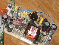
I've attached an image of my PSU, snipped from a larger picture of a dissected Ozzy. Hope this helps.

Tez
 

Attachments

  • osborne psu.jpg
    osborne psu.jpg
    97.4 KB · Views: 2
Just a quick update. Got up this morning and powered up the Osborne using SD system disk. No problems, ran WordStar v2, changed data disks, etc.

Rebooted with DD system disk, immediately formated a disk for DD, then did DiskCopy to put the entire DD system/help/util onto the new disk as a backup. Format was cranky (DD), but finalized a DD disk with a few E sectors (error, locked out). Could boot as DD system using that new copy of the system disk. Switched to another disk in B, and got "bdos error bad sector" on the new B disk. Immediately removed both disks and powered off (fearing I could corrupt the disks in the drives).

Tom

IMHO if your system is working fine in SD, then the disk drives are fine, ie, no fault with those. This is because SD is inherently less reliable than DD & SD requires tighter tolerances from your drives.

Philip
 
Thanks again gentlemen.

Now that I've heard my power cable is probably non-standard - and probably supplying less power to the main board than is required - I need to find out why the *standard* cable I have causes the system to freeze up. Even when it's plugged into the main board exactly like the non-standard cable that works reliably (at least in SD).

I'm betting that either there's a broken wire, or I've been putting it in backwards, just following the orientation the non-standard plug was installed before the "melt-down".

Anyone have a picture of the power cable connection to the main board? The white plastic socket that's right next to the disk drive cable connection on the main board - showing the orientation of those color wires?

Note that on the OCC1, the disk drives are actually powered through the ribbon cable, not through a separate power cable. Maybe my setup has been sending insufficient power through that "non-standard" cable ... and my "standard" cable is either screwed up or installed backwards.

Thanks.
Tom
 
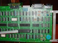
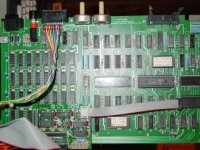
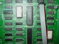
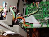
Here's some photos of my double density upgrade board.

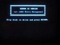
One thing - I've read bits and pieces of this post as I'm interested in Osbornes. I may have forgotton some of what I saw, and I don't want to have to go back through the 10 pages, but does this machine boot (when it does boot), to the normal Osborne screen?
Mine boots to the following screen, and then after hitting Enter I get the normal screen. I would suspect with a double density ROM that you shouldn't be getting the regular Osborne screen at the start (just a thought).

DSC01128 - comp.JPG

Here's the other photos of the board - are these what you were looking for?
If so, I've put them on my FTP site so you can grab higher res copies of them there.

DSC01115 - comp.JPG

DSC01117 - comp.JPG

DSC01118 - comp.JPG

DSC01122 - comp.JPG
 
Now that I've heard my power cable is probably non-standard - and probably supplying less power to the main board than is required - I need to find out why the *standard* cable I have causes the system to freeze up.

Not a bad idea to fix that harness. It might help to have a person helping. With the harness removed, one holds a probe on the power supply end while you probe the system board end. Flex the harness during the test to check for intermittent continuity. After that, you are not done. You need to check for shorts. While one person holds the probe on the power supply end, say the +5V line, you check for dead opens on the other lines (proper). If you get any signs of continuity, you may have a short. Check the AC/chassis ground lines too if you have a wire list or schematic for those lines.

Anyone have a picture of the power cable connection to the main board? The white plastic socket that's right next to the disk drive cable connection on the main board - showing the orientation of those color wires?

This may not be a problem if it is not keyed. The system board power connector seems to be a 7 pin connector that is wired symmetrically. From the manual, the end pins 1 & 7 are both red wires that have the +12V. Pins 2 & 6 should be yellow wires that carry the +5V. Pin 3 & 5 are orange and have the common return lines. Pin 4 is chassis ground. So it seems to me that it will work plugged in either way. Do you agree? Verify before you plug it in or if yours is not to this color code.

Maybe my setup has been sending insufficient power through that "non-standard" cable ...

It may be OK. The best way to check is to measure the 5V somewhere on the system board. If it reads above +4.75V, it is probably OK. The 12V at the drives should read above 11.4V. But I don’t know how hard it would be to check these voltages with everything buttoned up.

If everything works OK when you clean the disk heads, it may be best just to leave good enough alone. Fix the spare harness for use when the Osborne next fails.
 
Lorne - thanks for the pictures. You've got a non-Osborne ROM (OzRom); I've got the standard Osborne 1.4 ROM, which supports DD but doesn't have the bells and whistles yours has. And that picture confirms what Dave and others have said; the power cable wires are symmetrical, so reversing isn't likely to be a problem.

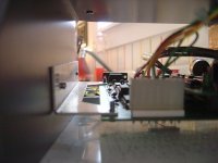
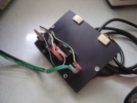
I've attached a picture of my own non-standard power socket, taken from the back of the board. Note the wires are red, yellow, orange, and green - and the green is jumpered into the next two holes. Now that's weird, as the center pin on the board is literally not connected to anything.

And yet, that non-standard cable is the one which works on my board; the standard cable (red, yellow, orange, blank, orange, yellow, red) results in the system being totally dead when powered up.

By the way, take a look at the second picture. The green wire on that non-standard plug runs *inside the harness* directly to the main power cord board (the red switch board); it's actually on a spade connector, connecting to a stud wired to the green/yellow wire coming off the incoming mains power. Now *that* seems totally bogus.

Edit: keep in mind that I'm working on my Osborne I, not a Ia. Serial number is A14649

Anyway, off to Sturbridge. Two new calves born Friday and Saturday.

T.
 

Attachments

  • scaled.DSC00367.JPG
    scaled.DSC00367.JPG
    29.9 KB · Views: 2
  • scaled.DSC00368.JPG
    scaled.DSC00368.JPG
    29.3 KB · Views: 2
Last edited:
I've attached a picture of my own non-standard power socket, taken from the back of the board. Note the wires are red, yellow, orange, and green - and the green is jumpered into the next two holes. Now that's weird, as the center pin on the board is literally not connected to anything.

By the way, take a look at the second picture. The green wire on that non-standard plug runs *inside the harness* directly to the main power cord board (the red switch board); it's actually on a spade connector, connecting to a stud wired to the green/yellow wire coming off the incoming mains power. Now *that* seems totally bogus.
Tom, it seems that a previous owner had to make some "workarounds" to fix some problem in the system. It appears to me that earth ground (Edison ground) has been routed directly to the DC common returns at the system board cable (pins 3 & 5). Perhaps this is an indication of a problem on pin 4 on the system board.

Usually for optimum system performance (lowest noise), a single point grounding scheme is employed to connect Edison ground to the chassis near the Osborne AC panel only.

Before you plug in the fixed power harness, you will now have to do some testing to see if there are lurking issues like shorts to pin 4 from who knows where. Old computers can be a series of complications.

So keep good notes on all this so you know where to start with a repair, but if the Osborne is working now to your satisfaction, I would follow the advise a Russian General Officer during the cold war whose motto was, "Better is the enemy of good enough".
-Dave
 
Osborne Information Gathered

Osborne Information Gathered

I threw together a quick website today to gather some of the excellent pictures and technical information that has been brought together in this thread. Thank you to everyone who has contributed. I put footnotes on the pics as to who provided them, I will do the same on request for the various PDF files

It can be viewed at.

http://retrocomputing.myauctionplace.com/osborne

-Lance
 
Nice page Lance,

Like people, these osbornes seem to get cranky with age, and it will be good to have a central website with a lot of this info on it.

Tez
 
Back
Top