• Please review our updated Terms and Rules here

Anyone else building an Apple-1 ?

I have my order in with Uncle Bernie, and I got the Sprague axial caps ordered from Unicorn. It's starting to get exciting!

My biggest hurdle is going to be finding a cheap keyboard. Seems like the going rate for Apple ][+ boards is $200, and older ASCII boards way more than that. I might put a post out to the Apple II Facebook group to see if someone has a spare they're willing to part with for a reasonable price.

As you say, not cheap but about the best $/age if you want a reasonable facsimile
 
Not much progress but transformers and switches wired up and all but one resistor soldered in. Missing a 27k one and period cf ones are hard to find but found a spare.

Almost ready to power up to check the regulators.

20220608_172529.jpg
 
Thought I was missing a resistor in UB's kit, but the two resistors for the oneshot 74123 are separate and packaged with the IC itself, so if you have one of these kits, dont get confused :)
 
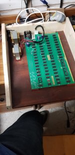
Build almost completed

Board powered up with all components except IC's fitted and all rails checked and bob on.

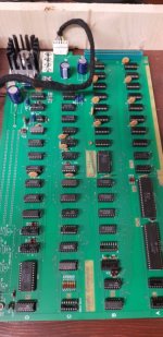
Uncle Bernie's kit is supplied row by row with the correct orientation so its a simple matter of picking out and fitting

Fitting the chips.jpg

And now everything fitted.

Complete circuit board.jpg

Want to do a complete check of all chips and orientation before powering on though and I need to make up a video cable.
 
I have built several Apple 1 clones and several replica 1 kits also.

This website ( not mine ) has a lot of good information about how the apple 1 hardware works that I have not seen anywhere else:

 
Cheers, appreciated.

Tomorrow is looking like the switch on date but that will be a 'standard' setup with none of the 'reliability mods' that are suggested by the kit supplier, so it might be a bit crash happy.

Then I need to decide if to use the Apple ][ keyboard that has a working encoder with a suitable cable, or to use the keyboard that's missing an encoder with the modern encoder that can wire directly to an Apple-1 and allows it to operate the reset and clear lines without an extra key or button.

Think I'm favouring the new encoder as it would be totally hidden below the keyboard.
 
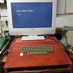
Powered up and running. Did have a problem with a screen full of $ instead of spaces. Looking as ascii, only one bit different. Found a small bit of solder residue bridging a couple of pins on the underside of the shift register and removing that gave me a clear screen :)
 
I've gone with the encoder adapter that interfaces an Apple ][ keyboard with the A1. I like the idea that Shift-reset operates the clear screen and reset operates the reset without having to include a separate button or bodge one of the A2 switches.

Just going to take some time to get here :(

I have ordered a 40mmx400mmx20mm 24V DC fan (https://uk.rs-online.com/web/p/axial-fans/6688814/) that is thin enough to hide in the back panel and cover with a stainless steel filter guard (https://uk.rs-online.com/web/p/fan-filters/0482130/)

I can then rectify the 24AC from one transformer with a simple half wave and a capacitor for a bit of smoothing and it should work ok.

The question is, to suck or to blow.

If I suck, some of the airflow will miss the big heatsink and pull from the adjacent hole for the boards edge connector, probably meaning some sort of baffle arrangement, if I blow then the heat from the heatsink will be shared around.

I know that a lot of A1's were passive, but I think a fan is important for reliability in a thick wooden box.
 
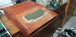
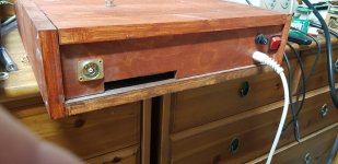
Case almost complete


20220626_112527.jpg

20220625_121824.jpg

Bit of staining around the keyboard and cleaning up, then Just waiting on the keyboard encoder to be delivered now.
 
Last edited:
Nice job.

Ergonomically designed as well :)!

Dave

Cheers, just need one of the little Sony monitors from the Active waste building now.

And, it needs a fan. The main regulator just gets to hot to be acceptable with convection.
 
Fan in.

Just a small 24V DC unit that I intended to pickup 24V AC from the power plug and just do a simple diode to 1/2 wave rectify it. Oddly it didn't seem to like it and refused to run. In a flash of inspiration, connected it without the diode and it runs from AC absolutely fine. No idea what happened to it but it works perfectly.
The main regulator now keeps ~30C as it only needed a small airflow to keep cool.

ACI fitted but unable to access the PROM. Jumper from R to C fitted (doh) and now that works, just need to test it now.
 
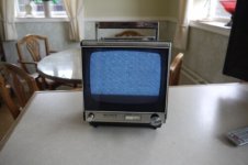
Looking for a period monitor and found this


Sony TV.jpg

Its a TV, but there is a circuit diagram available to modify it to put a simple buffer amp in to allow composite video.

Should look the part and it was really cheap.

Trick seems to be to look for 'solid state TV' on ebay.
 
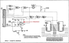
On thing I am having trouble with the the Cassette interface.

It uses a flipflop to drive a square wave and the signal coming out of that is fine (little bit noisy but ok)

I then goes into a very simple voltage divider with a 10K resistor into a 100ohm resistor meaning that the 5V square wave should become a 49.5mV signal suitable for a tape recorder Mic input.

What I actually see is noise with no discernible waveform and even then as a signal its not enough to be even picked up by my PC's Mic input.

Anyone know the standard voltage range of a PC's Mic input ? Im using a Ugreen USB device that uses a Cmedia HS100B chip but I cant find the input spec.

Can up the value of the 100ohm resistor to create a bigger signal of course.
 
You usually have some form of mic/line adjustment in the software.

The line input setting is (generally) something like 500 mV or 1V. The microphone input setting is something more sensible.

There is also usually some form of level/volume control on the PC.

Can I suggest opening the Windows mixer or some sort of control panel window that comes with the driver software?

Just out of interest, have you checked the voltage across the 100 Ohm resistor with an oscilloscope WITHOUT the PC connected?

It also depends upon the input impedance of the input as well - as this will affect the potential divider. Usually (old) cassette inputs were a high input impedance - so would have negligible effect on the signal level.

Dave
 
The value is 49mV by calculation, ie (5V / 10100) * 100. When physically measuring, the 5V TTL wave form from the flipflop is nicely formed with a bit of noise, but at the mid point of the divider, its all noise (with or without the lead plugged in).
Of course, the noise should be in the same SNR as the signal from pin 5 of the flipflop but it isn't. The signal isn't visible at all and its all noise. Seems a bit odd as I am scoping from ground to the mid point of the divider, where has all the noise come from.

The recommended recorder from 1976 has an input range of about 40mV but I do wonder how it ever worked if the signal is this

Not sure if the UGREEN USB adapter is a line input or an actual mV Mic input, but I'm suspecting a line input (never used it before)

I will probably I increase the value of the 100ohm resistor I will get the signal to match the input of the device.

ACI-schematics.jpg
 
There is a PCB track forming the 10k, 100R and output network isn't there?

Possibly a via is not making contact, or a damaged PCB track?

Are you sure it is a 100 Ohm resistor?

Are you sure the 10k resistor is not open circuit, or the 100R resistor not short circuit.

Just trying to cover all bases!

Dave
 
:)

Measured both resistors, ok
Measured from the mid point of the divider to the main board ground, 100ohm and from the output of the flipflop to ground 10100 ohms.

Going to replace both resistors with metal film ones but first will put a trim pot in instead of the 100ohm and see what signal my laptop is expecting then replace it with a fixed resistor.
 
Ah ha, the noise is on the ground between the scope and the boards ground. No idea where the noise is being generated but it explains why the SNR changes between the 5 and the 50mv.

Shouldn't affect the battery laptop as long s the signal is strong enough.
 
Back
Top