• Please review our updated Terms and Rules here

Arduino keyboard emulator host wiring.

Witchy

Experienced Member
Joined
Oct 11, 2015
Messages
376
Location
Flatlands, UK
Hi folks,

I have a UK rarity in a Tandata PA 'personal organiser' and viewdata terminal, the keyboard PCB of which has been eaten by battery leakage - it's lost several copper pads and some of the interlink traces have disappeared too. Deeming it too expensive to repair/replace I'm looking at an arduino replacement since it's a 12x12 passive matrix so there's no intelligence in there.

I've already drawn up the matrix and made up a little keyboard so I could use basic controls, cursor keys etc, and that works fine. I have an Arduino PS2 converter sketch that I can program to output either the PS2 key pressed or a code and I could easily wire up something like an Arduino Mega to control the 12x12 matrix, but how do I do this safely without possibly breaking the PA's motherboard or Arduino? The PA's PSU can easily run both and they're both 5V devices so there shouldn't be an overvoltage problem, I'm just exercising caution.

TIA!
 
I assume you mean the Arduino Mega 2560. If running directly from a 5V supply, it can handle 5V on its ports. If driving through its regulator, it needs a source of at least 7 volts. What voltages doe the PA use? Typically one side of the matrix is strobes while the other side is inputs. You might want to check to see which is which.
Using a Arduino Mega 2560 is over kill for this job.
If using the onboard regulator, remember current from outputs being pulled high go through the regulator while pull downs are through ground. I've seen many examples putting excess current on the supply line unnecessarily when a slight change in design makes it ground current instead.
Dwight
 
I'll put in a plug for the STM32 "blue pill". There's even an Arduino version for that family:

https://www.stm32duino.com/

Because it has an on-board 3.3V LDO regulator, it runs fine from 5V. Overkill (72MHz, 20KB RAM 256/512K flash)? Depends on your point of view--at sub-$3 price level for a complete system in a 40-pin DIP outline, it's hard to beat.

It does have 5V tolerant I/O. If you set said I/O to open-drain and use a resistor to pull up to 5V, you can span the entire TTL voltage range. Plus, you get 3 USARTs and USB, in addition to an ADC.
 
I wrote that first message in a hurry at work based on old notes, I agree the Mega is overkill but that was my thinking back in January when I first had this idea. Since then I've been given the schematics courtesy of an ex-Tandata staffer and tonight discovered the keyboard circuit is only 15 pins, not 24 which means I can use an Arduino Nano to do it I think. The PA only has 2 power inputs, around +16V and +8V which go to 7812 and 7805 regulators respectively with a further 7905L (I think, it's been a while since I looked) to generate -5V for the 4116 RAM chips in there. I was planning on running the Arduino using its VIN pin from the 5V rail rather than the regulator.

I've just noticed the keyboard circuit itself is based around 3x CD4051 analogue multiplexers (http://www.ti.com/lit/ds/symlink/cd4051b.pdf), is that going to cause me an issue?
 
Yep, I'm just about to scan it. The whole schematic is only 2 A3 sheets so it won't take long.

I've seen you mention the Blue Pill in other postings, well worth investigating. It's a shame the forum you linked to is going read only next month then closed down but there are others.
 
You can program the blue pill from the Arduino EDI, but it may require changes to port setup and such. I like the blue pill myself but I don't write in C ( unless I'm payed to do so ) and don't use the Arduino interface. I do have code that will take a ps/2 keyboard input, for a parallel keyboard output. I don't currently map every key to something on the parallel but these can be easily added.
One cool thing you can do with any of these is connect them to a SD card and have stored strings to do particular functions.
Dwight
 
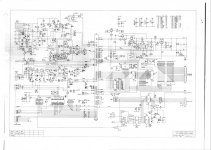
One analogue circuit schematic, will it let me put it as an inline image?

tandataPASchematics-01.jpg

Yes it will, sweet.
 
I'm afraid, the resolution isn't high enough to make out any of the writing. Can you blow up the portion of the picture that has the keyboard circuit and post again?
Dwight
 
Not good. It is a touch tone signal. I thought it was just a regular keyboard. I assume from the pinouts that the two chips connected to the keyboard are 4051s? Z2 is a little more complicated than a regular cross matrix. What is Z2??
Dwight
 
Hi Chuck
I was typing while you were posting. It looks like the pinout matches the 5089. Jameco has a pdf for it. I'm looking is it right now. There is a signal on Z5 pin 1 that I don't yet understand. Maybe the pdf will explain.
Dwight
 
It seems that the 5089 isn't really part of the keyboard decoding per se, as the only output seems to be the DTMF tone for dialing.

There's a connector to the left of Z6 that I'm having trouble figuring out.
 
I think we need to see the keyboard. It my look like a regular matrix but actually the keys are normally like a double pole switch with a common ground. In other words there are two separate contacts being made, not just two lines connected together.
Dwight
 
Back
Top